Download
1 / 17
170 likes | 329 Vues
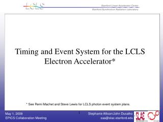
Timing and Event System for the LCLS Electron Accelerator*. * See Remi Machet and Steve Lewis for LCLS photon event system plans. Outline. Introduction Architecture and Pictures Issues and Tasks. LCLS Introduction.

E N D
Timing and Event System for the LCLS Electron Accelerator* * See Remi Machet and Steve Lewis for LCLS photon event system plans.
Outline • Introduction • Architecture and Pictures • Issues and Tasks
LCLS Introduction • The Linac Coherent Light Source is an X-ray FEL based on the SLAC Linac: • 1.0nC, 14GeV e- are passed thru an undulator, a Self Amplifying Stimulated Emission process produces 1.5 Angstrom X-Rays. • LCLS is an addition to the existing SLAC Linac: it uses the last 1/3 of the machine • This is important to note because we have to integrate the New LCLS Timing System with the Existing Linac (SLC) Timing System.
Existing SLAC Timing System • The Linac is a Pulsed Machine (get a packet of beam per pulse) runs at a max of 360Hz (120Hz) • Three Main Timing Signals: • 476MHz Master Accelerator Clock (runs down 2mile Heliax Main Drive Line cable) • 360Hz Fiducial Trigger (used to ‘tell’ devices when the beam bunch is present) / encoded onto the 476MHz master clock • 128-Bit PNET (Pattern Network) Digital Broadcast (contains trigger setup, beam type & rate information) • Existing system used for RF modulator triggers.
LCLS Timing System • Old CAMAC System is no longer viable for new Systems (performance limited, obsolete) • Seek to implement a new Timing System that has similar functionality, better performance, and can be laid atop the old system, working alongside it • In addition, LCLS has its own master oscillator (PLL sync’d with Linac MO) and local phase reference distribution system at S20 • LCLS Electron Accelerator is VME based (most CPUs are MVME6100), using High-Speed digital serial links to send Clock, Trigger and Data all on one optical Fiber to timing clients. Uses commercial hardware (MicroResearch Finland) • So far for the electron side, there are >80 EVRs (mostly PMC) and >10 fanout modules.
LCLS Timing/Event System Architecture Linac main drive line ~ Low Level RF FIDO PDU Raw 360 Hz LCLS Timeslot Trigger LCLS Timing System components are in RED 476 MHz LCLS Master Oscillator Sync/Div Linac Master Osc 119 MHz 360 Hz System is based around the EVent Generator and EVent Receiver SLC MPG P N E T I O C E V G F A N LCLS events SLC events fiber distribution Precision<10 ps * EPICS Network Digitizer LLRF BPMs Toroids Cameras Wire Scanner SLC klystrons I O C E V R D E V TTL * m P P N E T P D U TTL-NIM convert. SLC Trigs *MicroResearch
LCLS Systems – Master Timing Rack Master FODU Connects fibers to Long-Haul Trunks for entire machine Master Timing Crate • Contains: • VME CPU • VME PNET Rx • EVG • Master Fanouts 119MHz Synchronizer Chassis
LCLS Timing System – BPM Client BPM Crate w/VME-EVR Rx FODU & Fanout Crate Rear of BPM Crate / Showing Trigger Rear Transition Module
LCLS Timing System – Other Clients Toroid Crate w/PMC-EVR Profile Monitor Crate w/ (4) CPUs & PMC-EVRs MCOR Magnet Crate Rear of Toroid Crate / Showing Trigger Rear Transition Module
Event System Requirements • Event Generator IOC: • Send out proper event codes at 360Hz based on: • PNET pattern input (beam code and bits that define beam path and other conditions) • Add LCLS conditions such as BPM calibration on off-beam pulses , diagnostic pulse etc. • Future – event codes also based on new MPS and user input • Send out timing pattern, including EPICS timestamp with encoded pulse in nsec. part on timing fiber • Manage user-defined beam-synchronous acquisition measurement definitions
Event System Requirements, cont • Event Receiver IOC: • Set trigger delays, pulse widths, and enable/disable via user requests (not yet done on a pulse-by-pulse basis) • Set event code per trigger (triggering done in HW when event code received) • Receive timing pattern 8.3 msec before corresponding pulse. Provide EPICS timestamp to record processing. • Perform beam-synchronous acquisition based on tags set by EVG in the timing pattern. • Process pre-defined records when specific event codes are received – not used much yet.
EVR IOC Time Line – 1 Beam Pulse (B0) Record processing (event, interrupt) Hardware Triggers Receive pattern for 3 pulses ahead Triggering Event Codes Beam Kly Standby Event Timestamp, pattern records, and BSA ready Start End Acq Trigger Kly Accel Fiducial Event Received Fiducial Fiducial B0 F0 F1 … ~40 ~500 0 1023 2778 100 0.3 110 Time (usec)
Issues and Tasks • Modifications to EVG HW and firmware for 119MHz clock input and AC line input. • Had to power cycle a fanout module after an EVG power cycle. • Changing an event code for a specific trigger requires a change in the delay to trigger at the same time – need database to automate the change. • “Trigger Storms”: Due to LCLS Master Osc unlocking / Fix: New MO / De-Couple LCLS Timing Sys from it (connect direct to MDL). • Need interface to MPS over private UDP at 360hz. • Need global kicker control (single-shot, burst) done by EVG instead of locally. • Record processing at beam rate (up to 120hz) – some processing delays seen: • Too many records in one lockset. • Some records pick up wrong timestamp when delayed too long and data cannot be correlated with other data on other IOCs. • Some records need to have TSE field properly set. • Too many CA clients monitoring PVs at beam rate instead of snapshot PVs provided at a slower rate. • Not an issue but interesting - some beam diagnostic (ie, BPM) IOC engineers choosing to trigger at max possible rate and then use the timing data to decide if record processing required or to set record severity.
Linac Upgrade List • When 2 event codes trigger a device on the same pulse, the second event restarts the delay. The second event must be ignored instead. • Interrupt from the EVG on fiducial trigger (AC line trigger). • Diagnostics from the fanout modules. • Need status of the RF clock into the control system. • Upgrade front end timing hardware. • Move functions from the old timing system master pattern generator to the EVG IOC.