LCLS LLRF System
LCLS LLRF System. October 10-13, 2005 LLRF05 R. Akre, B. Hong, D. Kotturi, A. Hill, S. Heinz SLAC, Stanford, Menlo Park, CA 94025, USA. Outline. Overview of LCLS Injector RF System LCLS RF Stability Requirements Low Noise RF Distribution System RF Control and Monitoring System


LCLS LLRF System
E N D
Presentation Transcript
LCLS LLRF System October 10-13, 2005 LLRF05 R. Akre, B. Hong, D. Kotturi, A. Hill, S. Heinz SLAC, Stanford, Menlo Park, CA 94025, USA
Outline • Overview of LCLS Injector RF System • LCLS RF Stability Requirements • Low Noise RF Distribution System • RF Control and Monitoring System • RF Vacuum Interlocks • RF PPS Requirements
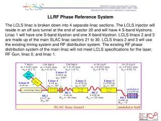
LCLS INJECTOR / LINAC • The LCLS linac consists of 4 sections. The injector L0 (2 S-Band Klystrons) willreside in anoff axis tunnel at the end of sector 20. L1 will have 1 S-band and 1 X-band klystron to feed their linacs, respectively. L2 (28 klystrons) and L3 (48 klystrons) are made up of the current main SLAC linac sectors 21 to 30.
LCLS RF Stability Requirements • Phase and Amplitude requirements by the physics design: • LCLS specifications require RF stability of 0.1%rms in amplitude and 100fSrms in a 850nS fill time S-Band structure, but the tightest tolerance is 125fSrms in a 100nS fill time X-Band structure. See Table on next page. • Bandwidths of the X-band System • Beam seen due to structure fill time ~ 10MHz • Structure RF Bandwidth ~ 40MHz • XL4 Klystron > 100MHz • Bandwidths of the S-Band System • Beam seen due to structure fill time ~ 1.2MHz • Structure RF Bandwidth ~ 16MHz • 5045 Klystron ~ 10MHz • The bandwidth for the system will be determined based on noise levels of the as built RF system and rise times of interest, somewhere between 1.2MHz and 10MHz.
RMS tolerance budget for <12% rms peak-current jitter (column 3) or <0.1% rms final e− energy jitter (column 4). The tighter tolerance is in BOLD, underlined text and both criteria, |DI/I0| < 12% and |DE/E0| < 0.1%, are satisfied with the tighter tolerance applied. All tolerances are rms levels and the voltage and phase tolerances per klystron for L2 and L3 are Nk larger, assuming uncorrelated errors, where Nk is the number of klystrons per linac.
Low Noise RF Distribution System • LINAC RF meets all LCLS specifications for 2 seconds when running well, but it is out of LCLS specs in 1 minute. • New phase lock oscillator will reduce the noise floor in the RF System. See next page. • The improved RF and Timing Reference System at the front end of the main linac and the new RF and Timing System at the end of sector 20 for LCLS L0 and L1 will reduce phase noise levels and eliminate the phase and frequency shift on the main linac. ? • The laser will be phase locked to the cleaned up. ?
Phase Noise of SLAC Main Drive Line Old Oscillator New Oscillator Noise Floor -120dBc/38Hz = -136dBc/Hz = 120fS rms Jitter in 5MHz BW Noise Floor -143dBc/38Hz = -158dBc/Hz < 16fS rms Jitter in 10MHz BW New Oscillators Have a noise floor of -157dBc/Hz @ 476MHz
LINAC Front End RF and Timing System? LCLS must be compatible with the existing linac operation including PEP timing shifts Master Oscillator is located 1.3 miles from LCLS Injector 1.3 Miles to LCLS Injector PEP PHASE SHIFT ON MAIN DRIVE LINE MDL RF with TIMING Pulse – Sync to DR
Linac Phase Reference System • Phase Reference Line • ½ inch Heliax Cable with 1.2 Watts • Phase Reference for 8 PADs (Klystrons) in the sector • Length = 1 Sector, 0.5 furlongs, 332ft, 400kS in ½” Heliax • Temperature Coefficient 4ppm/C • Waveguide Water T = 0.1C rms • 85% of the cable is regulated to 0.1C rms • 15% may see variations of 2C rms • Average Temperature Variation = 0.4C rms • = 0.64S rms • Main Drive Line • 3 1/8 inch Rigid Coax with 30watts input power 30mW out • Length = 31 Sectors, 15.5 furlongs 2miles, 3km, 1e7 S: Velocity = 0.98c • Anchored at each sector next to coupler and expansion joint • Purged with dry nitrogen • Phase Length Range 100S/Year • Phase Length Range 40S/Day • Accuracy Based on SLC Fudge Factor • 0.5S/Sector Total Variation • 0.2S rms / Sector
Linac Phase Reference System • Main Drive Line - 3 1/8 Rigid Coax Anchored to Concrete Floor Every Sector • Phase Reference Line - Each Sector Independent 1/2 “ Heliax • Must not introduce noise over 2 miles The PAD measures phase noise between the reference RF and the high power system. The beam sees 3.5uS of RF from SLED.
RF Control and Monitoring System • Bandwidth of S-Band System • Upper Frequency Limit – 10MHz • Beam seen due to structure fill time ~ 1.2MHz • Structure RF Bandwidth ~ 16MHz • 5045 Klystron ~ 10MHz • Lower Frequency Limit – 100kHz • Fill time of SLED Cavity = 3.5uS about 100kHz • Laser – Needs to be measured ~ 100kHz • Bandwidth of X-Band System?
Noise Levels • RF Reference Noise Floor • Oscillator -148dBc/Hz SSB at 2856MHz • RF -138dBc/Hz SSB at 2856MHz • Integrated Noise • -138dBc/Hz at 10MHz = -65dBc = 32fS rms • SNR = 65dB for phase noise • Added noise from MIXER (LO noise same as RF) • SNR of 62dB • ADC noise levels • SNR of 70dB – 14bit ADS5500 at 119MSPS 8.5MHz
RF Control and Monitor Points Summary • RF Gun 1 Klystron 3 RF monitors • Beam Phase Cavity 1 IQ modulator 1 RF monitor • L0-A Accelerator 1 Klystron 2 RF monitors • L0-B Accelerator 1 Klystron 2 RF monitors • L0-T Transverse Accelerator 1 Klystron 2 RF monitors • L1-S Station 21-1 B, C, and D accelerators 1 Klystron 4 RF monitors • L1-X X-Band accelerator X-Band • S25-Tcav 1 Klystron 2 RF monitors • S24-1, 2, & 3 Feedback 3 Klystrons • S29 and S30 Feedback 2 IQ modulators 476MHz • Totals 2856MHz 10 modulators 16 monitors
RF Monitor • LO 2830.5MHz : RF 2856MHz • IF 25.5MHz (8.5MHz x 3 in sync with timing fiducial) • Double-Balanced Mixer • Mixer IF to Low Pass Filter and Amp • Amp output to ADC (119MSPS or 102MSPS)?
SLAC Linac RF – New Control The new control system will tie in to the IPA Chassis with 1kW of drive power available. Reference will be from the existing phase reference line or the injector new RF reference I and Q will be controlled with a 16bit DAC running at 119MHz. Waveforms to the DAC will be set in an FPGA through a microcontroller running EPICS on RTEMS. Existing System
RF Sub-Systems • RF Gun • Beam Phase Cavity • L0-A Accelerator • L0-B Accelerator • L0-T Transverse Accelerator • L1-S Station 21-1 B, C, and D accelerators • L1-X X-Band accelerator • S25-Tcav • S24-1, 2, & 3 Feedback • S29 and S30 Feedback • The RF Monitor unit will be capable of measuring phase and amplitude for 2 RF channels. • The RF Control unit will be of two versions. The fast version will digitize a 1k sample of data to drive an IQ modulator. • The slow version will be capable of setting an I and Q value on a pulse to • pulse basis.
RF GunThe RF Gun will be driven from klystron 20-6. The RF monitors on the gun will be used in feedback loops to control the operating frequency along with providing phase and amplitude information to the longitudinal feedback.
Beam Phase CavityThe Beam phase cavity will be used to measure the bunch position relative to the RF. The measurement will be done at 120Hz and provide information to the feedback system. The cavity is located between L0-A and L0-B accelerator structures.
L0-A - First accelerator in the off axis injectorL0-B has the similar control scheme.
Injector Transverse Deflector CavityStation 20-5 and Station 24-8 will be connected to the new control system and used to drive the L0 and Sectpr 25 transverse deflector cavity, respectively. The cavity is used to deflect the beam with a deflection vs longitudinal position correlation. The beam is deflected to a screen where bunch length can be measured.
L1-SThe L1 linac consist of klystron 21-1 powering 3 accelerator structures in the main linac.
X-Band 2nd order correctionAn X-band accelerator structure will be located at station 21-2, just before BC1. The beam will be run on the decelerating crest to remove the second order curvature in the bunch vs longitudinal position correlation before compression in BC1.
S24-1, 2, and 3 (Three Units)Two klystrons in sector 24 will be used to correct the phase and amplitude of the RF as seen by the beam in LCLS L2 before the beam enters BC2. The klystron phase and amplitude will be adjusted based on bunch length and energy measurements. A third klystron will be capable of use by the feedback system if one of the other two should fail.
S29 and S30 Phase Control (Two Units)The phase of sectors 29 and 30 will be adjusted in opposite directions to change the average amplitude of the RF as seen by the beam as it passes through the sectors without effecting the average phase as seen by the beam.
RF Vacuum Interlocks • This requirement involves klystron stations 20-5, 20-6, 20-7, and 20-8 where new sections of waveguide will be added. • The long runs of waveguide will have ion-pumps with controllers. An interlock sum output of the controllers will be provided to tie into the 24 volt interlock chain of the associated Modulator Klystron Support Unit, MKSU. • Separate status lines with latches need to be available to determine where faults originate.
Sector 20 RF - PPS Requirements • In the main linac, all the klystrons will use the existing PPS system. For the klystrons operating the off axis injector in sector 20 the PPS system will require upgrades to allow access to the off axis injector during linac operation. Access to the linac will not be allowed during LCLS injector operation.