Advanced LLRF Phase Reference System for LCLS Linac
The new LCLS Phase Reference System integrates low noise oscillators, distributed to laser systems. It includes critical components, water-cooled plates, and RF signal distribution using advanced technology. The heart of the system is the LCLS Master Oscillator 476MHz PLL, ensuring precise phase stability and phase noise control.

Advanced LLRF Phase Reference System for LCLS Linac
E N D
Presentation Transcript
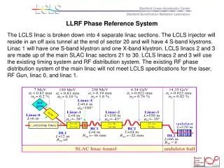
LLRF Phase Reference System The LCLS linac is broken down into 4 separate linac sections. The LCLS injector will reside in an off axis tunnel at the end of sector 20 and will have 4 S-band klystrons. Linac 1 will have one S-band klystron and one X-band klystron. LCLS linacs 2 and 3 are made up of the main SLAC linac sectors 21 to 30. LCLS linacs 2 and 3 will use the existing timing system and RF distribution system. The existing RF phase distribution system of the main linac will not meet LCLS specifications for the laser, RF Gun, linac 0, and linac 1.
LLRF Phase Reference System • A new LCLS Phase Reference System will include locking of a low noise osc. to the Linac RF Main Drive Line (MDL) reference. The LCLS 476MHz reference will be multiplied up to 2856MHz and then distributed to the gun laser, RF gun, L0-A, L0-B, transverse accelerator, L1-X and L1-S drive and monitoring systems. The electronics for this system will be housed in a temperature controlled room (+/-0.5C) that will enclose linac penetration 20-17. All of the phase critical heliax cables will be run down 20-17 when leaving the RF Hut. In addition all critical components will be mounted on water cooled plates with the water temperature being held to 0.3F. Andrews Heliax cable will be used to distribute the various RF signals.
LLRF Phase Reference System The heart of the Phase Reference System is LCLS Master Osc. 476MHz PLL. This chassis will use a Wenzel 119MHz crystal osc which will be multiplied up to 476MHz and then phase locked to the linac MDL. The Master Osc will require a track and hold to be built in and clocked by a linac timing system FIDO chassis at 120Hz. The LCLS will run at 120Hz using every 3rd cycle of the 360Hz linac timing signal. The oscillator's phase lock loop must track and hold at 120Hz in order to be phase stable during the 1/3rd of the time that the LCLS is running. During the other two thirds of the time the PLL will free run since the MDL will be changing in phase by as much as 720°. The phase noise of this system must be stable to within 50fS rms during LCLS beam time. A similar system is in use at SPPS. Beam to laser timing measurements show jitter of less than 150fS.
LLRF Phase Reference System The Wenzel Associates 119MHz crystal oscillator has the following specifications: Frequency: 119 MHz Level: +15 dBm ±2 dB into 50 ohms Aging: 1 x 10⁻⁶ per year after 30 days operating Temperature Stability: ±2 x 10⁻⁷, 0° to +50°C (Ref +25°C) Harmonics / Sub-Harmonics: <-30 dBc Mechanical Tuning: ±4 x 10⁻⁶ Electrical Tuning: ±5 x 10⁻⁷ Vibration Design: Vibration isolation system for best noise under vibration 30-45 Hz resonance Vibration Level: .005 g2/Hz, 40 to 1 kHz Phase Noise L(f): @119MHz@476MHz @2856MHz @11,424MHz 10 Hz -96 dBc/Hz 10 Hz -84 dBc/Hz 10 Hz -68 dBc/Hz 10 Hz -56 dBc/Hz 100 Hz -126 dBc/Hz 100 Hz -114 dBc/Hz 100 Hz -98 dBc/Hz 100 Hz -86 dBc/Hz 1 kHz -154 dBc/Hz 1 kHz -142 dBc/Hz 1 kHz -126 dBc/Hz 1 kHz -114 dBc/Hz 10 kHz -174 dBc/Hz 10 kHz -162 dBc/Hz 10 kHz -146 dBc/Hz 10 kHz -134 dBc/Hz 20 kHz -176 dBc/Hz 20 kHz -164 dBc/Hz 20 kHz -148 dBc/Hz 20 kHz -136 dBc/Hz
LLRF Phase Reference System Four different RF signals will be produced, amplified and distributed from the LCSL RF hut: 119MHz, 476MHz, 2856MHz, and the 2830.5MHz L.O. Two types of divide by 16 distribution chassis have been built. One type of chassis distributes the 119 and 476MHz signals and the other distributes the 2856 and 2830.5MHz signals. Both of these chassis use Pulsar Microwave ¸ 16 power dividers mounted on water cooling plates. The phase adjustment and amplification chassis for each frequency will include an IQ modulator for the phase control and a 2W amplifier. Each chassis will be connected to the LAN via a micro controller running EPICS. The controller will receive commands over Ethernet for adjusting the phase of the RF signal and a diode RF detector will be incorporated in each chassis to provide a RF power read back.
LLRF Phase Reference System The LCLS Local Oscillator (LO) generator will provide 2830.5MHz to the IQ demodulators located at each klystron station. The LO is generated by way of multiplying the 119MHz from the Master Osc up by 3 and then dividing that by 14. This creates a signal at 25.5MHz that is single side band modulated with 2856MHz creating the 2830.5MHz LO signal. This signal is then amplified and distributed to the demodulators via heliax cable.
LLRF Phase Reference System 2830.5 to 2856MHz Divide by 16 Chassis
LLRF Phase Reference System 119 to 476MHz Divide by 16 Chassis
LLRF Phase Reference System Linac Main Drive Line Coupler to be installed Oct. 2005