Download

1 / 33
330 likes | 451 Vues
This document provides a comprehensive overview of the LCLS Low-Level RF (LLRF) Control System's design. It outlines the system's scope, including RF phase and amplitude control across multiple locations, such as lasers and various klystrons. Key requirements include achieving stringent phase and amplitude noise levels, implementing a 120 Hz feedback loop, and adhering to LCLS Controls Group standards. The design considerations reflect evaluations of off-the-shelf versus in-house solutions, focusing on performance and cost-effectiveness. The LLRF system also integrates with beam-based longitudinal feedback and existing EPICS controls.

E N D
LLRF Control System • Outline • Scope • Requirements • Design Considerations • Evaluation • System drawings • How this fits into beam-based longitudinal feedback • Conclusions
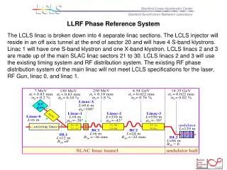
Scope • This document summarizes the design of the LCLS LLRF control system design including its interface with the beam-base longitudinal fast feedback.
Scope • The low level RF controls system consists of RF phase and amplitude controls at these locations: • Laser • Gun (Klystron 20-6) • L0-A, a.k.a. L0-1 (Klystron 20-7) • L0-B, a.k.a. L0-2 (Klystron 20-8) • L0 Transverse cavity (Klystron 20-5) • L1-S (Klystron 21-1) • L1-X (Klystron 21-2) • L2 - (Klystrons 24-1,24-2,24-3) to control avg phase/ampl of L2 • L3 Transverse cavity (Klystron 24-8) • L3 - 2 sectors of klystrons, S29+S30
Requirements (1) • Meet phase/amp noise levels shown below: • Table 1. RMS tolerance budget for <12% rms peak-current jitter (column 3) or <0.1% rms final e− energy jitter (column 4). The tighter tolerance is in BOLD, underlined text and both criteria, |DI/I0| < 12% and |DE/E0| < 0.1%, are satisfied with the tighter tolerance applied. All tolerances are rms levels and the voltage and phase tolerances per klystron for L2 and L3 are Nk larger, assuming uncorrelated errors, where Nk is the number of klystrons per linac.
ParameterSymbol|ΔI/I0| < 12%|ΔE/E0| < 0.1%Unitmean L0 rf phase (2 klystrons)00.100.10S-band degmean L1 rf phase (1 klystron)10.100.10S-band degmean LX rf phase (1 klystron)x0.50.5X-band degmean L2 rf phase (28 klystrons)20.070.07S-band degmean L3 rf phase (48 klystrons)30.50.15S-band degmean L0 rf voltage (1-2 klystrons)DV0/V00.100.10%mean L1 rf voltage (1 klystron)DV1/V10.100.10%mean LX rf voltage (1 klystron)DVx/Vx0.250.25%mean L2 rf voltage (28 klystrons)DV2/V20.100.10%mean L3 rf voltage (48 klystrons)DV3/V30.50.08%BC1 chicaneDB1/B10.010.01%BC2 chicaneDB2/B20.050.05%Gun timing jitterΔt00.80.8psecInitial bunch chargeDQ/Q02.04.0%
Requirements (2) • Achieve 120 Hz feedback to maintain phase/amp stability • Adhere to LCLS Controls Group standards: RTEMS, EPICS, Channel Access protocol • Begin RF processing of high-powered structures May, 2006
Local feedback loop requirements • At each of these locations, the klystron’s phase and amplitude will be monitored and controlled • When beam is present, control will be done by beam-based longitudinal feedback (except for T-cavs); when beam is absent, control will be done by local phase and amplitude controller (PAC)
Design considerations • Through end of January 2005, various solutions were evaluated, from 100% COTS modules to hybrids of in-house designed boards.
Narrowing down the options May/05 • Later, the options were narrowed down to two: an Off-the-shelf solution and an in-house solution. • This subset of options was presented at the Lehman Review, May 10-12, 2005. Ref: Low Level RF
Evaluation • The Off-the-shelf solution is: • Expensive ($25K per instance * 10 instances) • Noisy. ADCs are up to 150’ from what they measure so analog noise levels and ground loop problems would need to be dealt with • The in-house solution is: • Possibly longer to develop due to board design and fabrication time.
Evaluation (2) • Characteristics of the Off-the-shelf solution were seen as requiring more effort than those of the in-house solution • Potential offered by the lower cost of the in-house solution to replace 250 klystron controllers in the remainder of the LINAC is attractive • Hardware people were available as of 22aug2005 to work on board design if µcontroller was decided • Turned to the EPICS community for ideas and chose a µcontroller
Evaluation (3) • Lower cost alternatives to the $15K VME chassis and IOC were discussed in the session on hardware at the EPICS Collaboration Meeting. April 27-29, 2005 • Of the options available, only the Coldfire uCdimm 5282 processor had the communication speed and power to meet our data requirements. Cost is $150 per processor plus the development of the board it sits on
Evaluation (4) • By choosing the Coldfire processor, we are able to make use of the port of the operating system, RTEMS, which has already been done. • RTEMS is the standard for the real-time operating system chosen for LCLS by the Controls Group • EPICS, the standard for the control system software for LCLS runs on RTEMS • With these choices, the LLRF control system will be fully integrated into the rest of the LCLS EPICS control system and can speak to other devices and applications such as control panels, alarm handlers and data archivers, using Channel Access protocol, the standard communication protocol for this project.
Conclusions • This solution: • meets the spec for speed and noise • avoids signal noise problems • avoids ground loop problems • meets LCLS control system requirments and standards running EPICS on RTEMS • provides a low cost path for future upgrade in the rest of the LINAC when the rest of the klystron control is replaced
Conclusions • At 120 Hz, the LCLS LLRF raw signals must be processed, the phase and amplitude corrections must be sent out, applied and achieved • When there is beam, this system will integrate with the beam-based longitudinal feedback by accepting the latter’s RF phase and amplitude corrections and passing them on.