Digital LLRF feedback control system for the J-PARC linac
250 likes | 458 Vues
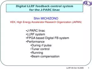
Digital LLRF feedback control system for the J-PARC linac. Shin MICHIZONO KEK, High Energy Accelerator Research Organization (JAPAN). J-PARC linac LLRF system FPGA based Digital FB system Performance During rf pulse Tuner control Running Beam compensation. What’s J-PARC?.

Digital LLRF feedback control system for the J-PARC linac
E N D
Presentation Transcript
Digital LLRF feedback control system for the J-PARC linac Shin MICHIZONO KEK, High Energy Accelerator Research Organization (JAPAN) • J-PARC linac • LLRF system • FPGA based Digital FB system • Performance • During rf pulse • Tuner control • Running • Beam compensation LLRF-05 Oct.10,2005
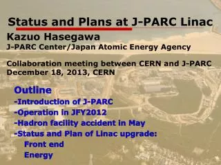
What’s J-PARC? J-PARC:Japan Proton Accelerator Research Complex • frontier science in particle physics • nuclear physics, materials science • life science and nuclear technology LLRF-05 Oct.10,2005
LLRF requirements • 190 MeV normal conducting proton linac • Operation frequency: 324 MHz • Total 19 klystrons (max.3 MW) • RF flat top: 650 us • Requirements of cavity electric field stability +-1% (amplitude), +-1deg. (phase) Klystron gallery Total 19 klystrons drive cavities LLRF-05 Oct.10,2005
Digital LLRF feedback control system for the J-PARC linac Shin MICHIZONO KEK, High Energy Accelerator Research Organization (JAPAN) • J-PARC linac • LLRF system • Performance • During rf pulse • Tuner control • Running • Beam compensation LLRF-05 Oct.10,2005
J-PARC LLRF system EPICS • cPCI digital FB system • generates LLRF signal (12 MHz, 48 MHz, 312 MHz and 324 MHz) • delivers I/Q modulated rf signals to 2 cavities • recieves rf signals from cavities and down-converts to IF • Fast hardwire interlock is connected to Pulse Modulator (outside cPCI). • Analog fast FB will be used for klystron FB loop. • Cavity-tuners are controlled from cPCI by way of PLC. LLRF PLC cPCI FB system LLRF-05 Oct.10,2005
cPCI digital FB system RF&CLK CPU Mixer&I/Q DSP/FPGA I/O Digital Analog cPCI is adopted for the crate. FPGA based digital FB system FPGA: Mezzanine card of the commercial DSP board • 2-FPGAs (2x VirtexII 2000) are installed with 4x14bit-ADCs and4x14bit-DACs at 48 MHz sampling • DSP board enables to calculate complex diagnostics such as cavity control. • FPGAs are used only for fast feedback. LLRF-05 Oct.10,2005
FB algorism RF:324MHz LO:312MHz IF:12MHz Sampling:48MHz IF signals are directly read by ADCs. The separated IQ signals are compared with set-tables and PI control is made with FF. LLRF-05 Oct.10,2005
Digital LLRF feedback control system for the J-PARC linac Shin MICHIZONO KEK, High Energy Accelerator Research Organization (JAPAN) • J-PARC linac • LLRF system • Performance • During rf pulse • Tuner control • Running • Beam compensation LLRF-05 Oct.10,2005
Vector Sum Control Amplitude:6,000 and Phase 0 deg. (I=6,000, Q=0) Vector sum control Set table is exponential function Agrees well with simulation LLRF-05 Oct.10,2005
External monitor Xtreme DSP board by Xilinx (commercial FPGA board with 66 MHz ADCs) External monitors are assembled with commercial fast FPGA board. The amplitude and phase stability is +-0.15%,+-0.15deg. LLRF-05 Oct.10,2005
FB stability Set value:6,000->5,000->4,000 With same FB parameters. FB works well with the amplitude variation of >20%. LLRF-05 Oct.10,2005
Digital LLRF feedback control system for the J-PARC linac Shin MICHIZONO KEK, High Energy Accelerator Research Organization (JAPAN) • J-PARC linac • LLRF system • Performance • During rf pulse • Tuner control • Running • Beam compensation LLRF-05 Oct.10,2005
Tuner control >1deg. Detuning, tuner control starts. Stop tuning control when the detuning becomes <0.2deg. A klystron drives 2 cavities. ADC_1,2:cavity field monitors ADC_3,4:cavity input monitors Detuning is calculated from the difference between input and cavity by DSP. -> Tuner control is carried out by DSP. Vector sum is stable even with 15 deg. detuning. Needs < 2 min. for control LLRF-05 Oct.10,2005
Digital LLRF feedback control system for the J-PARC linac Shin MICHIZONO KEK, High Energy Accelerator Research Organization (JAPAN) • J-PARC linac • LLRF system • Performance • During rf pulse • Tuner control • Running • Beam compensation LLRF-05 Oct.10,2005
Running data of J-PARC LLRF External monitor Internal monitor Cavity 1 Cavity 2 Vector sum ±0.5% ±0.5度 The trend of the average amplitude and phase (drift) The small drifts (<.2%,.2 deg. ) are caused by the temperature dependence of the rf circuits. These will disappear at the new version. Quite stable LLRF-05 Oct.10,2005
Digital LLRF feedback control system for the J-PARC linac Shin MICHIZONO KEK, High Energy Accelerator Research Organization (JAPAN) • J-PARC linac • LLRF system • Performance • During rf pulse • Tuner control • Running • Beam compensation LLRF-05 Oct.10,2005
Beam loading test Beam gate signal modulate the rf -> beam loading Beam loading observed at FB monitor Beam loading LLRF-05 Oct.10,2005
Beam loading test (cont.) Beam can be compensated with FF within +-0.3%,+-.15 deg. FB+ beam compensation FF Only FB beam beam +-5% +-0.5% +-2deg. +-0.5deg. LLRF-05 Oct.10,2005
Summary • Stability of <+-0.15%, +-0.15deg. is obtained during rf pulse with a SDTL test module. • Tuner control works well even from 15 deg. detuning position. • Eighteen hours running show good stability. • Beam loading test box enables to test the beam loading effects and the stability is ~+-0.3%, +-0.15deg. during beam pulse. • Linac commissioning will start from June 2006. LLRF-05 Oct.10,2005
Test cavity Ql=6,800 Test cavity Test cavity is quite useful for developing FB algorism. Step response LLRF-05 Oct.10,2005
Tuner control (1) Start: |error-set| > 3 deg. Goal: |error-set| < 0.2 deg. • Cavity tuner: Response ~100-500 ms • Communication between LLRF PLC and DSP: every 2 sec. (100 ms during tuner control) • Cavity input phase -> measured through FPGA2 • Cavity phase -> measured through FPGA1 • Phase error : calculated at DSP • If the detuning phase is far from set-phase • DSP will change the tuner through PLC until the detuning phase to be proper. 324 MHz LLRF-05 Oct.10,2005
Tuner control (2) NG OK Good OK NG Absolute error(common error < ±3deg.) • Compare rf phase between cavity-input and cavity. (->detuning) • Cavity tuner is controlled when the detuning is larger than set value (> 3 degree for common error and 1degree for relative error) -3 -0.2 0 +0.2 +3 (deg.) Tuner 1 (Δ1) (stop) move (control start) Tuner 2 (Δ2) (control start) move (stop) Relative error (Δ1-Δ2) (relative error < ±1deg.) Δ1-Δ2 -1 -0.2 0 +0.2 +1 (deg.) (control start) move (stop) LLRF-05 Oct.10,2005
Calibration • Amplitude in detector output is calibrated by comparing with FB monitor and detector monitor. LLRF-05 Oct.10,2005