LCLS LLRF Distributed Control System
LCLS LLRF Distributed Control System. Dayle Kotturi Controls Department SLAC National Accelerator Lab. LCLS LLRF Distributed Control System. Outline Scope Global Overview General stability requirements Principal motivator Solutions Throughput measurement Conclusions

LCLS LLRF Distributed Control System
E N D
Presentation Transcript
LCLS LLRF Distributed Control System Dayle Kotturi Controls Department SLAC National Accelerator Lab
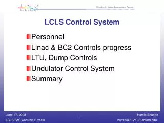
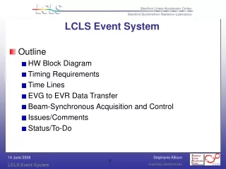
LCLS LLRF Distributed Control System • Outline • Scope • Global Overview • General stability requirements • Principal motivator • Solutions • Throughput measurement • Conclusions • Additional resources
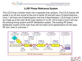
Scope • The low level RF controls system consists of RF phase and amplitude controls at these locations: • Laser • Gun • L0-A (a.k.a. L0-1) • L0-B (a.k.a. L0-2) • L0 Transverse cavity • L1-S • L1-X • L2 – using 2 klystrons to control avg phase/ampl of L2 • L3 Transverse cavity • L3 - here is a bit different (lots of klystrons!)
General stability requirements • For LCLS, the general RF stability requirements are: 0.1 deg phase and 0.1% amplitude in L0 and L1 for S band.
Principal motivator • Placing the digitizers next to the low noise RF components eliminates transmission of low noise analog signals outside the chassis.
OS, BSP and EPICS versions • PAD: • rtems4.9.1 • m68k uC5282 • epics-R3.14.10 • VME: • rtems4.9.1 • powerpc beatnik (mvme5500/mvme6100) • epics-R3.14.8.2 • PAC: • rtems4.9.1 • m68k uC5282 • epics-R3.14.10
Conclusions • At 120 Hz operation, time budget=8.333 ms • LLRF PAD->VME->PAC throughput measured=2.529 ms for 4 channels of 40 points each, with no offsets, • adjust: subtract 2.5 μsec per pair of IRQ raise/lower calls (8 pairs = 20 μsec) • adjust: one socket sends to multiple PACs; add switching time
Acknowledgements • Thanks to Ron Akre and Klystron Department for setting up hardware, scopes and signal generators • Thanks to SLAC NAL Controls Group
Additional Information • Details of the PAD->VME transfer • Details of the VME->PAC transfer • RF stability measurement • PAD • PAD Block diagram • LCLS LLRF website: http://www.slac.stanford.edu/grp/lcls/controls/global/subsystems/llrf
Details of the PAD->VME transfer • http://www.slac.stanford.edu/grp/lcls/controls/global/sw/epics/epics%20team%20meetings/presentations/lanIpBasic.pdf • Raw ethernet packets with IP and UDP headers. Similar to BSD sockets. • Solution is for low end CPU on small LAN. • Requirement: ship 1 KB of data in ~200 μsec • VME initializes, starts and stops PAD streaming • When PAD is streaming, device support for waveform on VME parses out the values and uses them in the feedback calculations of new setpoints.
Details of the VME->PAC transfer • On VME, a subroutine record that has calculated new setpoints calls a driver routine that sends the values to the PAC via udp socket • PAC is has thread waiting to receive packet • When packet arrives, it parses out the setpoints and puts them into mem mapped FPGA
LCLS Jitter Specification for 2 Seconds is 0.14% Amplitude and 0.14 degree Phase Feedback ON 20 Second Plot shows Phase Jitter 0.043 degrees Amplitude Jitter 0.022% Feedback ON 20 Second Plot shows Phase Jitter 0.043 degrees Amplitude Jitter 0.024% Short Term RF Jitter Specification for L0B are well Exceeded. This is as good as it gets – Don’t tell Physicists or they will expect it. Ron Akre 2007
About the PAD • CPU is MCF5282 (64MHz) • The digitizer used is the Linear Technologies LTC2208. It was the first 16 bit digitizer chip on the market capable of running at 119MHz, it is specified to run up to 130MHz. • At SLAC NAL, PAD digitizer used for RF, beam position monitors, beam charge monitors and bunch length monitors. • Pohang Light Source is also using PAD for new RF system.
Phase/amplitude detector (PAD) Block Ron Akre
LCLS LLRF Distributed Control System • Outline • Scope • General stability requirements • Principal motivator • Solutions • Throughput measurement • Conclusions • Additional resources
Scope • The low level RF controls system consists of RF phase and amplitude controls at these locations: • Laser • Gun • L0-A (a.k.a. L0-1) • L0-B (a.k.a. L0-2) • L0 Transverse cavity • L1-S • L1-X • L2 – using 2 klystrons to control avg phase/ampl of L2 • L3 Transverse cavity • L3 - here is a bit different (lots of klystrons!)
General stability requirements • For LCLS, the general RF stability requirements are: 0.1 deg phase and 0.1% amplitude in L0 and L1 for S band.
Principal motivator • Placing the digitizers next to the low noise RF components eliminates transmission of low noise analog signals outside the chassis.
OS, BSP and EPICS versions • PAD: • rtems4.9.1 • m68k uC5282 • epics-R3.14.10 • VME: • rtems4.9.1 • powerpc beatnik (mvme5500/mvme6100) • epics-R3.14.8.2 • PAC: • rtems4.9.1 • m68k uC5282 • epics-R3.14.10
Conclusions • At 120 Hz operation, time budget=8.333 ms • LLRF PAD->VME->PAC throughput measured=2.529 ms for 4 channels of 40 points each, with no offsets, • adjust: subtract 2.5 μsec per pair of IRQ raise/lower calls (8 pairs = 20 μsec) • adjust: one socket sends to multiple PACs; add switching time
Acknowledgements • Thanks as always to Ron Akre and Klystron Department for setting up hardware, scopes and signal generators • Thanks to SLAC NAL Controls Group
Additional Information • Details of the PAD->VME transfer • Details of the VME->PAC transfer • RF stability measurement • PAD • PAD Block diagram • LCLS LLRF website: http://www.slac.stanford.edu/grp/lcls/controls/global/subsystems/llrf
Details of the PAD->VME transfer • http://www.slac.stanford.edu/grp/lcls/controls/global/sw/epics/epics%20team%20meetings/presentations/lanIpBasic.pdf • Raw ethernet packets with IP and UDP headers. Similar to BSD sockets. • Solution is for low end CPU on small LAN. • VME initializes, starts and stops PAD streaming • When PAD is streaming, device support for waveform on VME parses out the values and uses them in the feedback calculations of new setpoints.
Details of the VME->PAC transfer • On VME, a subroutine record that has calculated new setpoints calls a driver routine that sends the values to the PAC via udp socket • PAC is has thread waiting to receive packet • When packet arrives, it parses out the setpoints and puts them into mem mapped FPGA
LCLS Jitter Specification for 2 Seconds is 0.14% Amplitude and 0.14 degree Phase Feedback ON 20 Second Plot shows Phase Jitter 0.043 degrees Amplitude Jitter 0.022% Feedback ON 20 Second Plot shows Phase Jitter 0.043 degrees Amplitude Jitter 0.024% Short Term RF Jitter Specification for L0B are well Exceeded. This is as good as it gets – Don’t tell Physicists or they will expect it. Ron Akre 2007