LLRF in FEL
260 likes | 497 Vues
LLRF in FEL. System sterowania parametrami fali stojącej z zakresu częstotliwości mikrofalowych w akceleratorach liniowych laserów na swobodnych elektronach. W. Cichalewski w imieniu grupy zaangażowanej w projekty FLASH/XFEL. Outline. - FEL at DESY Free Electron Lasers principles,

LLRF in FEL
E N D
Presentation Transcript
LLRF in FEL System sterowania parametrami fali stojącej z zakresu częstotliwości mikrofalowych w akceleratorach liniowych laserów na swobodnych elektronach W. Cichalewski w imieniu grupy zaangażowanej w projekty FLASH/XFEL
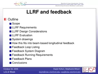
Outline - FEL at DESY • Free Electron Lasers principles, • FLASH/XFEL in numbers, - LLRF system structure and main functionality, - Cavities operation principles, cavity models, - Best cavity frequency tuning methods in presence of LFD and microphonics, - Fast feedbacks design and implementation in LLRF, - Vector sum control of single and set of modules for FLASH, XFEL, ILC, - High current beam operation, - Electron beam acceleration: LLRF control and beam optics adjustment, - FEL operation procedures for different experiments requirements, - Beam based feedbacks based on toroid, Beam Arrival Monitor, Beam Position Monitors, and synchrotron radiation detectors signals, - Global Optical synchronization system description for FLASH and XFEL - LLRF system at FLASH – current status, - Accelerator ambient radiation vs. performance of the accelerator electronics, - Conclusions... 2
Outline - FEL at DESY • Free Electron Lasers principles, • FLASH/XFEL in numbers, - LLRF system structure and main functionality, - LLRF system at FLASH – current status, - Area of DMCS main activities, - Future (next day, week, month, year....) - Conclusions... 3
SASE at Free Electron Lasers Free electron laser light generation using Self Amplified Spontaneous Emission Źródło: xfel.eu 4
European X-ray Free Electron Laser at DESY Źródło: xfel.eu 5
RF stations Accelerating Structures Diagnostics sFLASH Undulators Bunch Compressor Bunch Compressor LOLA RF Gun FEL Experiments 5 MeV 150 MeV 450 MeV 1250 MeV Bypass 315 m FLASH Źródło: S. Schreiber 6
LLRF system structure and main functionality Źródło:wikipedia MSK DESY 7
LLRF system structure and main functionality • Mission: • Generate RF signal for supplying superconducting cavities in cryomodules, • Optimize RF signal parameters (accelerating field amplitude and phase with respect to the electron beam) according to requested beam acceleration conditions 8
LLRF system functionality (POV beam operation) • Major issues: • Fast feedbacks for field parameters regulation (PID, MIMO, ...) • Adaptive algorithms for repetitive errors influence minimization • Beam loading compensation, • Loop gain and loop phase adjustment, • HPAC nonlinearites compensation, • Cavities resonance frequency control (piezo-based frequency regulation), • Interfacing to beam based feedbacks, Additional tasks • Modulations imperfections identification and compensation, • Calibration of HF signals drifts, 9
MSK group and DMCS cooperation areas • DMCS and DESY cooperation: • Most of above mentioned LLRF related topics for FLASH, • BBF design and implementation, • System radiation measurement, • Hardware/Software design and test of uTCA based system for FLASH and XFEL, • Continuous wave FEL operation (new), • Optical synchronization system (new), • Line detector for intra-bunch feedback (new). 10
LLRF system structure and main functionality 2 3 1 1. Field amplitude & phase regulation 2. Cavity frequency control with piezo actuators 3. Qext regulation, 11
LLRF system structure main hardware components Downconversion: - Downconverters, - direct sampling Upconversion: - Vector Modulator, - up-converter, Field parameters control: - filtering - realization of feedback algorithms, - realization of slow adaptive algorithms, - modulation imperfections reduction, - microwave ampl. nonlinearities compensation. Digital to analog conversion Signal discretization: - sampling, - averaging, - I/Q detection... 12
LLRF hardware systems at FLASH 10 Channel 14bit ADCs 81 MHz clock rate 8 DAC, 14 bits 2 Gigalinks FPGA: XILINX Virtex II pro DSP processor TS Źródło: H. Schlarb 13
Piezo actuators control system • Piezo drivers • new driver for ACC1 / ACC7 • DAQ server for detuning measurements • Several piezo studies performed • Active compensation of ringing • DC voltage added for static detuning Control software ~ 80 % completed But many features not fully commissioned Źródło: H. Schlarb 14
Beam Based Feedback implementation • Beam signals integrated • Charge signals • Bunch Arrival time • Pyro signal • Real time FB with matrix • Limiter on Ampl/Phase corr. • IIRF filters • Rep. rate adaption • Charge scaling of beam load compensation table Control software ~ 90 % completed Most of features are commissioned Źródło: H. Schlarb 16
High beam operation study towards XFEL/ILC Źródło: H. Schlarb
Continues Wave linac operation Źródło: J. Sekutowicz
Ongoing developments – ATCA system New standards under development for telecomunication purposes: Advanced/Micro Telecommunications Computing Architecture Main goal: Build modular, scalable control system suitable for FLASH/ XFEL modules control that follows current telecomunication standards and offers maximal system availability. ATCA based system development for two years resulted in: - hardware prototypes has been designed and lab tested (field controller, piezo controller), - software preparation, - no meaningful LLRF system operation in accelerator, but: - experience gained – needed for new uTCA based system development, - new project ITER. 19
Future (next week, month, year....) Next weeks: - debugging of controller board, - production and debugging of Vector Modulator board, - firmware download software commissioning, - front-end server preparation for LLRF controller - CW operation at CMTB, Next month: - first uTCA based system measurements at FLASH - KW 30-31(hardware and software has to be debugged by that time), - installation of uTCA based architecture in different FLASH modules, - CW operation at CMTB, Next year: …..... 23
Conclusions Main collaboration fields: - design, implementation and commissioning of software for: - accelerating modules field parameters control, - beam operation, - high level control algorithms for system parameters optimization and beam operation , - diagnostic of individual cavity and overall system performance, - fast cavity frequency control, - Beam based feedbacks, - optical system synchronization, - design, implementation and commissioning of hardware for: - piezo control, - line detectors, - realization of different controllers, - different experiments hardware set-up, software preparation and operation support. 24
To read..... Sth to read: - FLASH main page: http://Flash.desy.de - X-FEL main page: http://xfel.eu - Collaboration meeting in Cracov: https://indico.desy.de/conferenceTimeTable.py?confId=4086#20110418 - Long beam operation, https://indico.desy.de/conferenceOtherViews.py?view=standard&confId=3007 25
Thank You THANK YOU FOR YOUR ATTENTION 26