Download
1 / 8
90 likes | 190 Vues
Stay updated with the latest developments in the SP spectrophotometer electronics project. Follow the progress from testing to component selection and order releases. Key milestones and future plans shared.

E N D
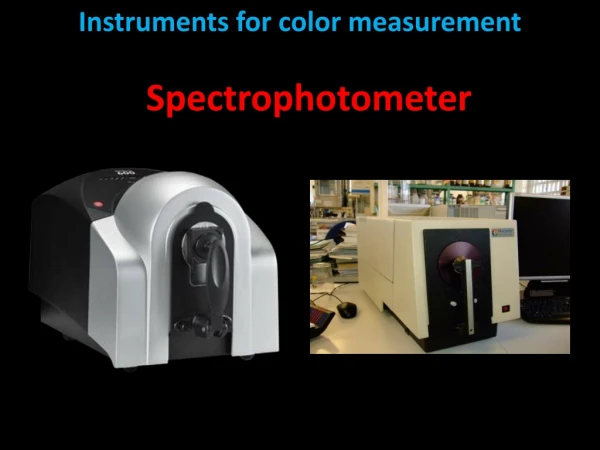
ISUAL Spectrophotometer Electronics C. Ingraham NCKU UCB Tohoku
SP Electronics Functions • Integrate and Sample PM Tube Output • Send Digitized Samples Serially to MM • Create Sprite “Trigger” Signal • Set Trigger Threshold • Receive CDI Commands from DPU • Provide Connections Among SP Subassemblies NCKU UCB Tohoku
SP Electronics Block Diagram Spectrophotometer Data Controller Block Diagram (One Channel of Six) NCKU UCB Tohoku
SP Electronics Interfaces • Six Buffered Analog Signals from PM Tubes • Serial Data to Mass Memory • CDI Commands from DPU • Sprite Trigger to DPU, MM • Six Lines to Stim LEDs • Six Filter Heater and Thermistor Connections • Two Survival Heater and Thermistor Connections • Electronics Power from Power Controller NCKU UCB Tohoku
SP Electronics (Analog) Board • Mounts Between SP Left & Right Halves • Mostly Connections • Six PM Tube Output Preamps • Six Stim LED Connections • Six Filter Heater and Thermistor Connections • Two Survival Heater and Thermistor Connections • +/- 12 Volts Analog Power from Power Controller • Filter Heater Power from Power Controller • Survival Heater Power from LVPS NCKU UCB Tohoku
SP Digital Electronics • On IDC Board • Integrates Charge from PMT • Samples at 1 Hz or 10 kHz per Channel • 12-bit A/D Converter per Channel • Sends Serialized data to MM Buffer • Digitally Processes Selected Channel for Sprite Trigger • Adjustable Trigger Threshold NCKU UCB Tohoku
SP Electronics Development Status (1) • Single-Channel Test Board Built • Ready for Test with PM Tubes • Analog Board Mechanical Design Complete • Analog Board Circuit Design due 5 March • Analog Board PCB Design to start 7 March • All EEE Parts Selected, Ordered, and Received NCKU UCB Tohoku
SP Electronics Development Status (2) • Drawings Released: • Analog PCB Outline (8621) • Analog PCB Schematic (8623) • Digital PCB Schematic (8544) • SP Test Board Schematic (8646) NCKU UCB Tohoku