Download
1 / 26
260 likes | 612 Vues
EEG Monitoring System. The EEG Porto-Cap™. Team 5 ENGN4017 - Engineering Design Autumn 1999. Design Process. Examine project domain EEG measurement systems Meet with intended customer Dr Richard Clark, Flinders University SA Identifying problems with existing skull cap system

E N D
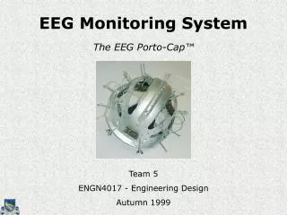
EEG Monitoring System The EEG Porto-Cap™ Team 5 ENGN4017 - Engineering Design Autumn 1999
Design Process • Examine project domain • EEG measurement systems • Meet with intended customer • Dr Richard Clark, Flinders University SA • Identifying problems with existing skull cap system • Requirements for new system were formulated • Develop conceptual solutions to problems • Brainstorming • Project Decomposition • Sub-system groups focussing on specific problems • Integration • System integration • Presentation, Final Report March June
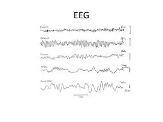
What is EEG? • EEG = Electroencephalogram • Measurement of brain wave patterns in hopes of understanding the mysteries of the mind.
Problem Statement The reliable measurement, over extended periods, of scalp EEG on consecutive occasions, during mental functions in everyday environments.
Key Problem Areas Issues that needed to be addressed in any new system developed by the group: • Lack of repeatability • Different Head Sizes • Long setup times • Difficulty with lengthy experiments • Use of conductive gels • Scalp abrasion • Noise in signal • Lack of portability/environmental constraints In finding a solution, we have taken an ambitious approach to solving these problems in a medical research application
M e c h a n i c a l Key Requirements
M e c h a n i c a l Cap Design
M e c h a n i c a l Current model. Nathan in an early model. Positioning • Nasion/Ear reference points • Adjustable straps for different head dimensions (53cm - 66cm) • Electrodes retractable to suit
M e c h a n i c a l Demonstration ofSkull Cap Setup . . .
E l e c t r o d e Key Requirements
E l e c t r o d e 2mm Electrode Selection • Silver/silver chloride selected • Minimal polarisation characteristic • Dry electrode used (no gel required) • Uses local impedance converting amplifier • Pellet electrode, 2mm diameter • Small electrode size ensures good hair penetration and contact with scalp
E l e c t r o d e Irritation Issues • Initial model- helmet supported by electrodes • Prototype - straps support the load • allows smaller electrodes to be used without increasing irritation • straps allow for more comfortable fit • No preparation or abrasion of skin surface required
E l e c t r o d e Cleaning • Electrodes detachable for cleaning • Cleaning processes include disinfecting and sterilisation via autoclave • Use of two sets of electrodes allows continuous use
S i g n a l s Key Requirements
S i g n a l s Components
S i g n a l s Signal Flow
S i g n a l s Signal Flow
S i g n a l s Signal Flow
S i g n a l s Signal Flow
S i g n a l s Other Features • EMF Shielding • Faraday cage • Cable shielding • Auto-Zero Function • Remove constant DC offset introduce by electronic components
Areas of Further Research • Gauging depth of electrodes • Improving setup time • Ag/AgCl dry electrodes • Electrode polarisation • Effectiveness of Faraday cage • Noise analysis • Artifacts from physiological rhythms
Manufacturing Materials Cost • Total - around US$4k • Mechanical - US$100 • Electrode - US$2300 • Signals - US$1800 • Prototype materials - estimated US$50k
Why you should upgrade to the Porto-Cap™ . . . • Wireless communication – no huge cables to lug around, you are free to walk around the house just like with a cordless phone. • Data recorded from each different electrode is clocked at exactly the same instant – at last, a device which accurately maps which bits of your brain that weren’t working during that embarrassing moment. • No scalp preparation required – the feeling of blunt needles scraping your scalp will only be remembered in your nightmares. • Porto-Cap™ uses dry electrodes only – that gooey conducting paste can now be used as axle grease. • Zero signal drift – the amplifier and filter package has been hand picked so that the only interruptions during a testing period will involve rubble entering your building. • Eight selectable sampling frequencies – if flexible data rates is you, then you won’t die hungry when wearing the Porto-Cap™.
Conclusion The EEG Porto-Cap™ successfully enables repeatable and reliable measurements of EEG signals. It achieves this with little discomfort, no paste or gel and in conventional environments.
Thank you for coming,we would like to take this opportunity to answer any questions you may have. Team 5 ENGN4017 - Engineering Design Autumn 1999