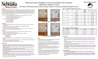
Tie Down Example
Tie Down Example. Understanding AS1684. Residential Timber Framed Construction. Split level house, Dutch gable roofs, C2 - Sheet roof. Bracing Example. 900. 1604. North elevation. C2 Split level Dutch gable roofs Ceiling height 2560 Eaves 600mm Roof pitch 25 o. 1038. 2077.

Tie Down Example
E N D
Presentation Transcript
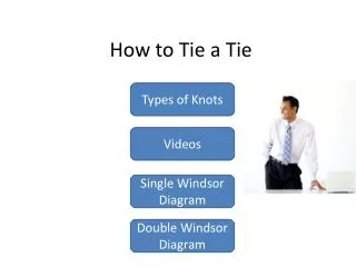
Tie Down Example Understanding AS1684 Residential Timber Framed Construction • Split level house, • Dutch gable roofs, • C2 - Sheet roof
Bracing Example 900 1604 North elevation • C2 • Split level • Dutch gable roofs • Ceiling height 2560 • Eaves 600mm • Roof pitch 25o 1038 2077 East elevation
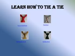
Level 2 Level 1 Wind direction 1 Wind direction 2 Level 1 and Level 2
Level 3 Level 3
Tie - Down Design Process • General • Prior to starting the detailed determination of tie-down connections etc, it is recommended that familiarization with Clauses 9.1 (pg 156) to 9.5 (pg 163) be obtained. • These clauses include, but are not limited to topics such as: • Corrosion protection • Washer sizes • Joining of top plates and • Nominal fixings etc • For example: See Washer sizes - next
Tie - Down Design Process Clause 9.2.4 Steel Washers (pg 157)
Tie - Down Design Process (Clause 9.3) 1. Determine if specific tie-down required Table 9.2 (pg 161) 2. Determine the wind uplift load width Clause 9.6.2 & Fig 9.5 (pg 163- 164) 3. Determine the uplift pressure Table 9.5 (pg 165) 4. Calculate the wind uplift force Clause 9.6.4 (pg165) 5. Determine the Joint Group Table 9.15, Fig 9.6 (pg 175 – 176) 6. Enter the appropriate design strength Tables 9.16 to 9.25 (pg 177 to 203) & select a suitable tie-down connection 7. Determine shear force Clauses 9.7.5 & 9.7.6 (pg 204 & 211) 8. Enter the appropriate design strength Tables 9.27 to 9.30 (pg 205 to 212) & select a suitable shear connection
Specific connections required 1. Determine if specific tie-down required a) Use Tables 9.2 (uplift) and 9.3(shear) to determine if Nominal and additional Specific fixings are required. AS1684.3 p161
Determine if specific shear connections • are requiredCont. Specific connections required AS1684.3 p161
1. Determine if specific tie-down requiredCont. b) Determine Nominal Fixing requirements. (Clause 9.5 & Table 9.4) AS1684.3 p162/163
Determine if specific tie-down requiredCont. c) Determine Specific Tie-Down Requirements • In this example, specific tie-down connections will be determined for : • roof batten to truss • standard truss to top plate/floor frame or slab • Dutch girder truss to floor frame • tie-down at sides of openings • floor frame to stumps/footings • Note: Not all tie-down connections required for the house will be covered by this worked example.
Determine if specific tie-down requiredCont. • (Roof battens to rafters/trusses) c) Determine Specific Tie-Down Requirements The area to be held down via roof battens is calculated by multiplying the: Batten Spacing x Tie - Down Spacing resulting in the area of roof acting on the Tie - Down connection at that point.
2. Determine the wind uplift load width/area (Roof battens to rafters/trusses) Wind uplift area = Batten Spacing x Tie - Down Spacing Wind uplift area of roof acting on batten tie-down: = 0.9m x 0.9m = 0.81m2 NOTE: Whilst in this example the roof batten spacing has nominally been specified as 900mm, in high wind and cyclonic areas, manufacturers specifications for the sheet roofing may require closer batten spacing to ensure satisfactory performance of the sheeting. Check manufacturers requirements
3. Determine the uplift pressure (Roof battens to rafters/trusses) Roof battens fall into 2 categories - 1. Within 1200 mm of edges 2. General area A different Net Uplift Pressure is applied to each category. (Table 9.5, pg 165)
3. Determine the uplift pressure (Roof battens - General areas and Edge areas)
3. Determine the uplift pressure (Roof battens to rafters/trusses)
4. Calculate the wind uplift force (Roof battens to rafters/trusses) Roof battens to rafters/trusses - Within 1200 mm of edges. Net Uplift Force = Wind Uplift Area of roof x Net Uplift Pressure 0.81m2 x 5.5 kPa (kN/m2) =4.46 kN
4. Calculate the wind uplift force (Roof battens to rafters/trusses) Roof battens to rafters/trusses - General Area. Net Uplift Force = Wind Uplift Area of roof x Net Uplift Pressure 0.81m2 x 3.49 kPa (kN/m2) = 2.83 kN
5. Determine the joint group (Roof battens to rafters/trusses) Select the appropriate Joint Group - 35 x 70 MGP10 seasoned pine batten (JD5) to MGP12 seasoned pine truss top chord (JD4). Joint Group = JD4 (truss specification) MGP10/JD5 MGP12/JD4 AS1684.3 p175/176
6. Select a suitable tie-down connection (Roof battens to rafters/trusses) Select a Tie-down connection - [Table 9.25] Batten to truss (within 1200mm of edges) Uplift Capacity = 4.46 kN Adopt - 1/75mm long, No.14 Type 17 screw JD4 Screws (length) J2 J3 J4 JD4 JD5 JD6 Diagram (d) 1/75 mm 5.7 4.2 2.4 4.5 3.6 2.7 38 x 75 or long ´ 38 50 mm batten 1/90 mm 7.4 5.5 3.2 6.0 4.7 3.6 long No14 Type17 screws 2/75 mm as per table 11 8.4 4.8 9.0 7.2 5.4 long Two screws shall be used only with 75 mm wide 2/90 mm 15 11 6.4 12 9.4 7.2 batten long AS1684.3 p202
6. Select a suitable tie-down connectionCont. (Roof battens to rafters/trusses) Select a Tie-down connection - [Table 9.25] Batten to truss (General Area) Uplift Capacity = 2.83 kN Adopt - 1/75 mm long No.14 Type 17 screw, as there are no nailing options available that achieve the required load. Therefore use same fixing over whole roof.
6. Select a suitable tie-down connectionCont. d) Determine specific tie-down requirements where appropriate. For all other connections (truss to wall frame, wall frame to floor), the following inputs are required... i) Uplift Load Width ii) Uplift Area (or tie-down spacing) iii) Wind Uplift Force iv) Joint Group
6. Select a suitable tie-down connectionCont. i) Uplift Load Width. This is used to determine the tie-down requirements for each structural joint, excluding roof battens. (Clause 9.6.2 and Figure 9.5, pages 163 & 164) AS1684.3 p 163/164
6. Select a suitable tie-down connectionCont. ULW for roof and wall frames Indicates Tie-down connections ULW for floor frames (c) Roof truss construction FIGURE 9.5 ROOF UPLIFT LOAD WIDTH ULW AS1684.3 p164
L living/ dining C ‘ULW’ (5100 mm)
6. Select a suitable tie-down connectionCont. (Roof trusses to wall frame) The Uplift Load Width (ULW) will be determined across the lounge/dining area of Level 2. This is the “worst case” and will be applied throughout the structure for convenience. The width is 7.710/2 m + 1.2 m (cantilevered section for verandah) and therefore the truss ULW is5.055, say 5.1 m
6. Select a suitable tie-down connectionCont. (Roof trusses to wall frame) ii) Uplift Load Area. This is calculated by multiplying - ULW x Tie - Down Spacing = ULA
6. Select a suitable tie-down connectionCont. (Common trusses to wall frame) Uplift load width (‘ULW’) = 5100 mm Truss spacing (tie-down spacing) = 900 mm ULA = 5.1 m x 0.9m = 4.59 m2
6. Select a suitable tie-down connectionCont. (Roof trusses to wall frame) iii) Wind Uplift Force. We now require a pressure to use in selecting the connection. This can be determined by multiplying the - Uplift Load Area x Net Uplift Pressure (Table 9.5) for the joint in question. (Clause 9.6.4 and Figure 9.5) AS1684.3 p 165
6. Select a suitable tie-down connectionCont. (Roof trusses to wall frame)
6. Select a suitable tie-down connectionCont. (Roof trusses to wall frame) Wind Uplift Force: = Uplift Load Area x Net Uplift Pressure Rafters/Trusses to wall frames - Top and bottom plates to studs. Wind Uplift Force = 4.59m2x 3.25 kN/m2 (kPa) = 14.9 kN AS1684.3 p 165
6. Select a suitable tie-down connectionCont. iv) Joint Group. This is the rating assigned to a piece or parcel of timber to indicate the design capacity appropriate to that timber for a range of connectors. (Clause 9.6.5 & Table 9.15) F5/MGP10 seasoned softwood framing is likely to contain pith, MGP12 seasoned softwood framing should be free of pith. AS1684.3 p 175
6. Select a suitable tie-down connectionCont. Where a timber joint is comprised of two or more different species, the joint group allocated to that joint shall, in general, be that appropriate to the weakest material in that joint (Clause 9.6.5) AS1684.3 p 175
Joint group (J, JD rating) shall be based on this member as design strength is controlled by the nails working in shear (a) Joint type 1 Joint group (J, JD rating) shall be based on the weakest of either member as design strength is controlled by shear or bearing of the bolt in both members (b) Joint type 2 Joint group (J, JD rating) shall be based on this member as design strength is controlled by the shank of the nail or screw in withdrawal (c) Joint type 3 AS1684.3 p 176
Large arrows indicate direction of load. AS1684.3 p 176
6. Select a suitable tie-down connectionCont. d) Select tie-down connections.
6. Select a suitable tie-down connectionCont. Discussion • When selecting a suitable tie-down system for the trusses/rafters to the floor frame or slab, a decision is required on whether: • a direct tie-down system will be used • connect trusses direct to floor frame or slab or • connect trusses to top plate and then within 100 mm of truss, connect top plate to floor frame or slab OR • Indirect tie-down by connecting trusses to top plate and then top plate to floor frame or slab located anywhere i.e. not within 100 mm of truss to top plate connection. • For option 1. the top plate is not required to resist the wind uplift bending forces, and may be sized accordingly. • For option 2. the top plate must be sized to account for uplift bending so tie-down spacing becomes important.
6. Select a suitable tie-down connectionCont. Discussion – tie-down options Up to 450 mm for rods at 900 crs Trusses fixed to top plate/ribbon plate with various fixings eg framing anchors, straps, bolts etc 100mm max Tie-down rods at say 900 mm crs but not within 100mm of truss Direct tie-down Top plate size not governed by tie-down spacing In-direct tie-down Top plate designed to resist uplift, by tie-down spacing required
6. Select a suitable tie-down connectionCont. (Common trusses to top plate) (see Table 9.21) Required uplift capacity = 14.9 kN Joint Group = JD4 (assume MGP12 softwood wall framing) Adopt – Two looped straps with 4/2.8 ø nails to each end. (25 kN) AS1684.3 p 194
6. Select a suitable tie-down connectionCont. (Common trusses to wall frame alternative tie-down) (A range of additional tie-down options is available for high wind areas - also, see manufacturers or industry published literature such as from the Timber Queensland Data Sheet below) Required uplift capacity = 14.9 kN Joint Group = JD4 (assume MGP12 softwood wall framing) Adopt – 12 mm cuphead bolt through angle bracket plus M12 tie-down rod. Timber Queensland Tech Data Sheet
Timber Queensland (TRADAC) Tech Data Sheet
6. Select a suitable tie-down connectionCont. (Wall top plate to bottom plates/slab) (see Table 9.19, pg 186) Required uplift capacity = 14.9 kN @ 900 crs Joint Group = JD4 (softwood) Adopt – M10 tie-down bolt with 38 x 38 structural washers at 900mm crs (see Table 9.1 [pg 157] for washer size) capacity 15 kN. Where trusses are tied direct to floor/slab, then this alternative tie-down would not be used. Note: 1. If the tie-down crs from top plate to bottom plate are increased, this will impact upon the required top plate size as it will mean it is spanning further in the wind uplift mode. 2. In cyclonic areas, a min of M12 rods are normally readily available and used JD4 AS1684.3 p 186
6. Select a suitable tie-down connectionCont. (Dutch girder truss to wall frame) 2400 Uplift load width (‘ULW’) = 5100 mm 450 1645 2360 5055 900 300 ULA = 5.1m x 0.9m (blue) + 3.56 m x 0.75m (red) + 1.2 x 0.45 (green) – 0.3 x 0.3 = 4.59 + 2.67 + 0.54 - 0.09 = 7.7 m2 approx. 900 900 300
6. Select a suitable tie-down connectionCont. (Dutch Girder to wall frame) Wind Uplift Force: = Uplift Load Area x Net Uplift Pressure Dutch girder wall frame. Wind Uplift Force = 7.7m2x 3.25 kN/m2 (kPa) = 25 kN AS1684.3 p 165
6. Select a suitable tie-down connectionCont. (Lintels and studs at sides of openings to Floor Frame or Slab) Dutch Girder 2400 mm setback approx Common trusses @ 900 crs M12 cuphead 14.9kN ↑ 25kN ↑ 14.9kN ↑ See next for size of rods 200 mm approx M10 or M12 rods Check Lintel support detail later Verandah 18 24 sw
6. Select a suitable tie-down connectionCont. (Dutch Girder to wall frame) Dutch girder to lintel. Assume lintel and Dutch girder are MGP12/JD4 minimum. Required uplift capacity = 25 kN Use 2/M12 rods/bolts through MS plate, capacity 40kN JD4 AS 1684.3 pg 194
6. Select a suitable tie-down connectionCont. (Dutch Girder to wall frame) As the Dutch girder lands over an opening, the loads from it plus the common trusses that also land over the opening have to be distributed to the tie-down either side of the opening. The loads should be distributed to each side in approximate proportion to the amount that is going to be resisted by tie-down at each side. In this example, assume all the load from the Dutch girder goes to the RH side tie-down, 50% of the middle common truss goes to both sides and all the load from the LH common truss goes to the LH side of the opening. AS1684.3 p 165
6. Select a suitable tie-down connectionCont. (Lintels and studs at sides of openings to Floor Frame or Slab) 200 mm approx M10 or M12 rod 14.9kN 100% 25 kN 100% 14.9kN 50% to each side 32.45 kN Say 33 22.35 kN Say 22 Verandah 18 24 sw
6. Select a suitable tie-down connectionCont. (Tie-down at sides of opening) Sides of openings, assume JD4 Required uplift capacity = 25 kN to LHS and 33 kN to RHS Use M16 rods either side Allowable capacity 35 kN. Note the bolt and jamb stud arrangement required for this detail. AS 1684.3 pg 188