Acceleration Sensor SPI Emulator
UNIVERSITATEA “POLITEHNICA” DIN TIMIŞOARA FACULTATEA DE ELECTRONICĂ ŞI TELECOMUNICAŢII DEPARTAMENTUL DE ELECTRONICĂ APLICATĂ. Acceleration Sensor SPI Emulator. Thesis adviser: Associate Professor Ph.D. Eng. JIVE Ţ Ioan. Author: MIH ĂILESCU Andrei-Bogdan. TIMIŞOARA 2010.

Acceleration Sensor SPI Emulator
E N D
Presentation Transcript
UNIVERSITATEA “POLITEHNICA” DIN TIMIŞOARA FACULTATEA DE ELECTRONICĂ ŞI TELECOMUNICAŢII DEPARTAMENTUL DE ELECTRONICĂ APLICATĂ Acceleration Sensor SPI Emulator Thesis adviser: Associate Professor Ph.D. Eng. JIVEŢ Ioan Author: MIHĂILESCU Andrei-Bogdan TIMIŞOARA 2010
Acknowledgement The present diploma project has been developed in the period 15th September 2009-30th June 2010 as a research project in collaboration with “Politehnica” University Timişoara, „eAustria” Research Institute Timişoara and “BeeSpeed Automatizări” Timişoara (as a subcontractor for TRW, CIAT department, from Koblenz, Germany).
Presentation Overview • Why this project? • Architecture overview • Sensor • CPLD • Microcontroller • Big Picture • Questions
Why this project? • Title explanation SPI (Serial Peripheral Interface) with 2. Target use
Sensor VTI SCA2120-D07 Accelerometer:
CPLD • Xilinx XC95288XL CPLD: • 6 ns. pin to pin login delay • System frequency up to 208 Mhz • Available in 144 pin TQFP package (easy soldering, even by hand) • Low power operation • 5V tolerant I/O pins accept 5V, 3.3 V and 2.5 V signals • In-system programmable • Local clock inversion with 3 global and 1 product-term clocks • Full IEEE Standard 1149.1 boundary scan (JTAG) • 6400 usable gates • 288 macrocells
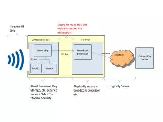
uC-CPLD SPI timing diagram MISO Data VSC CPLD MOSI uC Sync VSC_CLK CLK_C164 CSB MISO Sensor CPLD role • Operation: • -Step 1: ‘understand’ request from the VSC • -Step 2: see if data is available from the uC or information is to be parsed directly from the sensor • Step 3:send the data to the VSC.
uC • uC Board: • TQM164C minimodule • uC Role: • ADC port information • CAN (Controller Area Network) • Hardware-in-the-Loop interface • Transmission of simulation values • To the CPLD (3-wire SPI)
uC-CPLD SPI timing diagram X_axis Data A D C Input Y_axis Sync Z_axis Temperature CLK CAN uC Role ADC information processing: Acceleration: Voltage range is 0…3.3V. 0g value = 1.65 V Resolution: 0.59V/g Temperature: Voltage range is 0… 3.3V 23°C value= 1.65 V Resolution: 10mV/°C
“Big picture” CPLD uC Sensor ADC interface
Conclusion TRW Hardware-in-the-Loop System • Circuit capabilities: • Simulation capabilities of the acceleration sensor • Analogical input for simulation values thru ADC port; • Fault injection capabilities • CAN simulation values injection and debugging (in progress) • Integration with Hardware-in-the-Loop system for TRW