Download
1 / 23
230 likes | 447 Vues
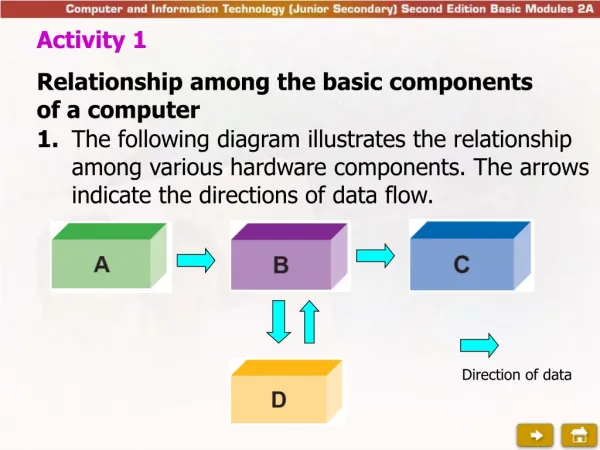
Data Handling and Filter Framework for the D0 L3/Trigger System. Gennady Briskin, Brown University. CHEP 2000, February 7 - February 11, 2000, Padova (Italy), Abstract 377. A. Boehnlein G. Briskin G. Brooijmans D. Claes D. Cutts S. Mattingly M. Souza G. Watts. The DØ Trigger System.

E N D
Data Handling and Filter Framework for the D0 L3/Trigger System Gennady Briskin, Brown University CHEP 2000, February 7 - February 11, 2000, Padova (Italy), Abstract 377. A. Boehnlein G. Briskin G. Brooijmans D. Claes D. Cutts S. Mattingly M. Souza G. Watts
The DØ Trigger System Detector Trigger Full Readout Information DAQ ~7 MHz ~1 kHz Level 1 Level 3 ~10 kHz ~50-70 Hz Level 2 C/R ~1 kHz RIP Tape Output
Run II DAQ Numbers • Readout channels: • Will be ~800,000 in Run 2 • <250 kBytes>/event • Data rates: • 60-80 readout crates • Many to one: • All GS to one of 64 L3 farm nodes • Initial design capacity: • ~1000 Hz • 250 MBytes/sec into the DAQ/l3-farm • Staged upgrades to more than 3 GB/sec
L3 Node (1 of 16) L3 Node (1 of 16) L3 Node (1 of 16) L3 Node (1 of 16) S (4 DATA CES L3 Node (1 of 16) L3 Node (1 of 16) ) Front End Token Readout Loop Front End Token Readout Loop Front End Crate Front End Crate Front End Crate Front End Crate VRC 1 VRC 8 Front End Crate Front End Crate Primary Fiber Channel Loop #8 Front End Crate Front End Crate Primary Fiber Channel Loop #1 SB 1 SB 4 Event Tag Loop Ethernet Ethernet ETG To Collector Router To Collector Router Trigger Framework Segment Data Cables Segment Data Cables ) )
L3 Filter L3 Filter L3 Filter Process L3 Farm Nodes L3 Node Framework VME Crate Each 48 MB/s Control, Monitoring and Error Module MPM Node-VME I/O Module 100-BaseT Ethernet MPM DMA capable VME-PCI Bridge Shared Memory Buffers Collector Router Module L3 Filter Interface Module • Input rate starts at 1000 Hz • Output rate is ~50-70 Hz • Intel Based SMP System • Windows NT • As many L3 Filters as possible • Prototype hardware in hand Dedicated 100 Mbits/s Ethernet to Online Collector/Router
L3 Node Requirements • What we really need for L3 node is: • To serve the interrupt efficiently • Low overhead for process scheduling and context switching: threads • Low overhead for Inter-Process Communication: shared memory • Low overhead for thread/process synchronization: events, mutexes, etc... • Efficient extension to multi-processor environment • Full functionality of Network OS • Directory sharing, etc…
NT OS Characteristic • WinNT is highly responsive NOS created by developers of VMS • WinNT has some real time characteristics • NT is preemptive multitasking and multi-threaded • Scheduling items are threads and the context-switch overhead is low. • NT offers SMP support, with Interrupt Dispatch Table configurable for individual processors • NT supports 32 priority levels • 16 of these are fixed real-time priority levels • NT supports Asynchronous I/O • NT processes can lock themselves into memory • Avoids paging while doing real-time work to improve predictability of response time • Other considerations • The Win32 API is becoming a de facto standard • GUI is very popular • NT has a lot of commercial solutions (h/s-ware) • Great number of development tools are available
L3 Node Data Path • L3 Node is where for the first time in the DAQ system all the data for a single event is assembled together. • Once an event has been copied into memory, don’t move it again • Pass pointer to an event in a shared memory around • Use a pipeline architecture with a thread for each task • Thread-safe queues between the tasks to manage the event pointers • Physics Filter executes in a second process • Isolates the framework from crashes • Write protected shared memory, i.e. prevents corruption of raw data. • Simple IPC mechanisms
L3 Supervisor Interface L3 Filter Output Interface L3 Node FrameWork Control Pool Queue MPM Reader Event Buffer Shared Memory • Get a pointer to an event buffer • Configures MPMs for receiving new event • Wait till complete event arrives into MPM • Load event data into shared memory buffer • Insert event pointer into the next queue Data L3 Filter Input Interface Validation Queue L3 Filter Process Process Interface Event Validation • FECs presence validation • Checksum validation Filter Queue Process Interface Output Events Queue Output Pool Queue Command/Monitor/Error Shared Memory L3 Monitor Interface Collector/Router Network Interface L3 Error Interface • Determine where this event should be sent • Sent event to collector/router node Data to Online Host System
Software Issues • Interrupt Handling • Memory Management • L3 Filter Environment
Interrupt Management • In real-time applications it is critical thatinterrupts be handled promptly. • NT handles interrupts on preemptive basis. When an interrupt occurs, all execution at lower levels is suspended and execution begins immediately on the highest-level request. Processing continues until the highest-level interrupt is complete. • In SMP environment:kernel dispatches the interrupt to just one CPU, all other CPUs continue executing uninterrupted (L3Filter Process) High 31 Power Inter-processor notification Processor A Clock IRQL Device n Device n . . . Interrupt masked on Processor A Processor B IRQL Dispatch/DPC Dispatch/DPC Interrupt masked on Processor B APC 0 Passive_Level
VME/PCI VME Bridge MPM MPM MPM MPM Interrupt Test • It is important to see if L3 Node can respond to an event and meet the real-time requirement of reacting within a prescribed time limit to that event • Need to measure Interrupt to Task Start • We used a Dual Pentium II clocked at 333 MHz and connected to VME via VME/PCI bridge. • We used VMETRO board to observe signals on a VME backplane.
Interrupt Test • While performing the tests, the system was loaded artificially with one REAL_TIME (31) process and applications using network/disk transfers. • The acquisition thread (with dynamic priority) was blocked, waiting for the event object to be signaled that interrupt has occurred and then issue a read to Multi Memory Board in the VME crate. • We observe first read on backplane ~135us (max 225us) • This involves ISR, context switch and read request to Device Driver
Memory Management • WinNT is built around a virtual memory system and can address up to 2 GB. • Windows NT memory management allows for memory mapping, which permits multiple processes to share the same physical memory. This results in very fast data transfers between cooperating processes or between a driver and an application. Memory mapping can be used to dramatically enhance real-time performance. • Windows NT permits an application to lock itself into memory so that it is not affected by paging within its own process. • Paging I/O occurs at a lower priority level than the real-time priority process levels; this really ensures that background virtual memory management won't interfere with processing at real-time priorities.
Shared Memory • IPC between processes is done via shared memory Event 1 L3 Node Process Event . L3 Filter Process Event . Event n Shared memory Test on single Pentium Pro clocked at 200 MHz have shown that we can pass a pointer to an event in shared memory between processes at ~4000 events/sec using event objects for synchronization.
L3 Filter Level 3 Node L3 Framework (drives & organizes data + handles communications with outside) Data In Data Out L3 Filter reject 19/20 events, based on full event reconstruction
L3 Filter Environment • L3 Filter Shell provides calling sequence to ScriptRunner public interfaces • Event data passed into ScriptRunner as anedm::Event • Read only access to Raw Data • Add result chunks to theedm::Event • No Network or Disk Access during regular running • Exceptions can be made during calibration runs • No direct access to COOR • Parameters and filter scripts provided by the L3 framework • Alarm system access is via the Error Logger Package
ScriptRunner Filter Scripts (and Filters) Tools ScriptRunner Candidate objects Trigger decision Correspond to the L3 triggers, call filters, which call tools to reconstruct the event Handles communication with L3 framework, calls appropriate filter scripts (based on L1/L2 bits that fired), takes care of initialization, and of run, ... Perform event reconstruction, call other tools (e.g. electron tool will call calorimeter clustering, which will call calorimeter unpacking)
Start Run Chronology • Start Run download trigger list • Extern Iterator asks L3 parser to instantiate tools and filters • Tools are instantiated through their pseudo-constructor, getting their parameters, and pointers to tools they need through the parser • Same for Filters, but they are associated with a link node in a Linked List ( Execution tree)
Event Chronology • For each active and fired L2 bit, traverse the corresponding level 3 branches (multiple branches per L2 bit are possible) • Done by following the Linked List, executing the corresponding filters (which execute the tools etc.) until one fails • If all pass, build L3Chunk • Execute Full Reset
In Run • Can change prescale factors • Can add/drop L2 bits from active list • Can enable/disable L3 bits • Can request summaries/statistics • ...
Conclusion • C++ Reuse is depended upon heavily to get the project done on time • Small general components in many of the nodes will be reused. • Objects have really helped us out. • Design to Windows OS strengths • Data Handling Framework is finished • ScriptRunner Framework is finished • Cosmic Muon tests with a complete L3 node will start next week
The valiant warriors of D0 are strong thanks to a magic potion prepared by druid Getafix and this recipe is secret (all we know is that it has lobster and beer)


![[f´‚nE˘RIks]](https://cdn0.slideserve.com/1072532/f-ne-riks-dt.jpg)


![[f´‚nE˘RIks]](https://cdn2.slideserve.com/5310017/f-ne-riks-dt.jpg)