Exploring the World of Wireless PANs: Embracing Bluetooth Technology
Dive into the realm of Wireless Personal Area Networks (WPANs), where short-range wireless connections redefine communication between devices, such as replacing cables with the industry standard Bluetooth technology. Understand the IEEE 802.15 Working Group's efforts to standardize WPAN protocols and interfaces, ensuring seamless connectivity within a PAN network. Learn about the diverse task groups from medium-rate to high-rate WPAN standards, coexistence practices, and mesh networking possibilities. Discover the benefits of WPANs for personal, professional, and industrial applications, offering enhanced connectivity within a 10-meter personal operating space. Immerse yourself in the history, technology, and myriad applications of Bluetooth, the wireless communication pioneer that revolutionized how devices interact.

Exploring the World of Wireless PANs: Embracing Bluetooth Technology
E N D
Presentation Transcript
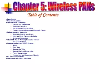
Chapter 5: Wireless PANs Table of Contents
Introduction • WPANs are short to very-short range wireless networks(from a couple centimeters to a couple of meters) • WPANs can be used to replace cables between computers and their peripherals • The IEEE 802 has established the IEEE 802.15 WG for WPANs, which standardizes protocols and interfaces for WPANs • The best example representing WPANs is the industry standard Bluetooth, which can be found in many consumer electronics
WLAN and WPAN Standards Note: As of March 2006, the 802.15.3a task group has been officially withdrawn from the IEEE Operating space of the various IEEE 802 WLAN and WPAN standards and other activities still in progress
The IEEE 802.15 Working Group for WPANs • A single WPAN is intended to be a network in the home or office with no more than 8 to 16 nodes and altogether, 802.15 WG is formed by five TGs: • IEEE 802.15 WPAN/Bluetooth TG 1 (802.15.1) – The TG 1 was established to support applications which require medium-rate WPANs (such as Bluetooth); these WPANs handles a variety of tasks ranging from cell phones to PDA communications, have a QoS suitable for voice applications and this TG is derived a Wireless Personal Area Network standard based on the Bluetooth v1.1 specifications • IEEE 802.15 Coexistence TG 2 (802.15.2) – Several wireless standards, such as Bluetooth and IEEE 802.11b, and appliances, such as microwaves and cordless phones, operate in the unlicensed 2.4 GHz ISM frequency band and the TG 2 has developed recommended practices to facilitate collocated operation of WPANs and WLANs to promote better coexistence of IEEE 802 wireless technologies,
The IEEE 802.15 Working Group for WPANs • IEEE 802.15 WPAN/High Rate TG 3 (802.15.3) – The TG 3 for WPANs has defined standards for high-rate (from 55 Mbps up to 480 Mbps) WPANs and besides a high data rate, this standard provides for low power, low cost solutions addressing the needs of portable consumer digital imaging and multimedia applications • IEEE 802.15 WPAN/Low Rate TG 4 (802.15.4) – The TG 4 has defined a standard having ultra-low complexity, cost, and power for a low-data-rate (200 Kbps or less) wireless connectivity among fixed, portable, and moving devices as location awareness is considered as a unique capability of the standard, potential applications include sensors, interactive toys, smart badges, remote controls, and home automation • IEEE 802.15 WPAN/Mesh TG 5 (802.15.5) – The TG 5 is chartered to determine the necessary mechanisms that must be present in the PHY and MAC layers of WPANs to enable mesh networking which is a PAN that employs one of two connection arrangements: full mesh topology or partial mesh topology
Why Wireless PANs • WPAN devices are typically smaller, operate on battery power, and are either worn on a human body or carried personally • The main design goal of WPANs is to allow devices that are in close proximity to communicate and exchange information with each other, either stationary or moving • A WPAN is functionally similar to a WLAN, while differs in terms of power consumption, coverage range, data rate and the cost
Why Wireless PANs • WPAN should allow devices to create or provide data/voice access points, personal ad hoc connectivity and be a replacement for having connecting cables • The operating range for these devices is within a personal operating space (POS) of up to 10 meters in all directions, and envelops a stationary or a mobile person • The concept of a POS can also be extended to devices such as printers, scanners, digital cameras, microwave ovens, TVs or VCRs • As WPANs use the license-free radio frequencies (e.g., ISM band), they have to coexist with other RF technologies that make use of these frequencies
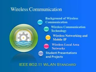
The Bluetooth Technology • Bluetooth (or simply BT) has been a topic of considerable buzz in the telecommunications industry for the past few years • Bluetooth is named after a 10th-century Viking king known for his success in uniting Denmark and Norway during his rule around 960 AD • Bluetooth is a low cost and short-range radio communication standard that was introduced as an idea in Ericsson Laboratories back in 1994 • Engineers envisioned a need for a wireless transmission technology that would be cheap, robust, flexible, and consume low power
Applications of Bluetooth Some application areas where Bluetooth networks could be explored • Consumer – Wireless PC peripherals, smart house wireless PC peripherals, smart house integration, etc. • Games – Controllers, virtual reality, iPODs, etc. • Professional – Pagers, PDAs, cell phones, desktops, automobiles, etc. • Services – Shipping, travel, hotels, etc. • Industry – Delivery (e.g., scanners, printers), assembly lines, inspections, inventory control, etc. • Sports training – Health sensors, monitors, motion tracking, etc. • Military – Combat and maintenance
Bluetooth – Technical Overview • The Bluetooth Specification (version 1.1) describes radio devices designed to operate over very short ranges – on the order of 10 meters – or optionally a medium range (100 meters) radio link capable of voice or data transmission to a maximum capacity of 720 kbps per channel (with a nominal throughput of 1 Mbps) • Radio frequency operation is in the unlicensed ISM band at 2.4 to 2.48 GHz, using a frequency hopping spread spectrum (FHSS), full-duplex signal at up to 1600 hops/seconds • The Bluetooth specifications are divided into two parts: • The Core – This portion specifies components such as the radio, base band (medium access), link manager, service discovery protocol, transport layer, and interoperability with different communication protocols • The Profile – The Profile portion specifies the protocols and procedures required for different types of Bluetooth applications
Bluetooth – Technical Overview • Whenever a pair or small group of Bluetooth devices come within radio range of each other, they can form an ad hoc network without requiring any infrastructure • Devices are added or removed from the network dynamically and they can connect to or disconnect from an existing network at will and without interruption to the other participants • In Bluetooth, the device taking the initiative to start communication to another device assumes the role of a master, while the recipient becomes a slave • The basic architectural unit of a Bluetooth is a Pico net, composed of one master device and up to seven active slave devices, which can communicate with each other only through their master
Bluetooth Piconet An example of a Piconet
Bluetooth – Technical Overview • Every Bluetooth device is exactly the same except for a 48-bit device identifier (BD_ADDR) • Besides up to 7- active slaves, additional devices can be connected to a Piconet in a parked state in which they listen but do not participate • When they want to participate, they are swapped in and one of the active devices is swapped out • If the acting master leaves the Pico net, one of the slaves assumes its role • With this method, up to 255 devices can be virtually connected to the Piconet • Also, each piconet uses a different Frequency Hopping Sequence (FHS) in order to reduce interference with other nearby piconets • To increase the number of devices in the network, a scatternet architecture consisting of several piconets has been proposed
Bluetooth Scatternet • A scatternet comprised of three piconets • Since scatternets span more than a single piconet, therefore a few nodes act as bridges (e.g., B12, B13, B23) responsible for relaying packets across piconet boundaries
Frequency Hopping HOP SELECTION Native clock phase HOP sequence Master Identity BD_ADDR offset
Master identity selects a unique hop sequence • Clock determines the phase (explicit hop) in the sequence • The sequence cycle covers about 23 hours • On average, all carriers are visited with equal probability • The number of hop sequence is very large • If every participant on a given channel uses the same identity and clock as input, then each unit will consistently select the same hop channel and remain synchronized.
Clock synchronization • Every Bluetooth unit has an internal clock called the native clock (CLKN) and a Bluetooth clock is derived from this free running native clock • For synchronization with other units, offsets are added to the native clock to obtain temporary Bluetooth clocks (CLK), which are mutually synchronized • When a piconet is established, the master’s native clock is communicated to all its slaves to generate the offset value
Slaves’ Derived Clocks • Every slave unit participating in a piconet uses the derived clock (CLK), for all timing and scheduling activities in the piconet
Bluetooth – Data types • The Bluetooth specification defines two different types of links for data and voice applications: • The Synchronous Connection Oriented (SCO) link • SCO link is a symmetric, point-to-point link between the master and one slave • Usually, the SCO link is used for audio applications with strict Quality of Service (QoS) requirements • The Asynchronous Connectionless (ACL) link • ACL link is treated as a packet switched, point to point and point to multipoint data traffic link • The master maintains one ACL link with each active slave over which upper layer connection can be established and re-transmission is employed only when it is necessary to ensure the data integrity
ACL ACL ACL ACL ACL ACL SCO SCO SCO SCO SCO SCO Physical Link Types • Synchronous Connection Oriented (SCO) Link • Slot reservation at fixed intervals • Asynchronous Connection-less (ACL) Link • Polling access method m s1 s2
Packet transmission in Bluetooth • A TDD scheme divides the channel into 625 sec slots at a 1 Mb/s rate • As a result, at most 625 bits can be transmitted in a single slot • However, to change the Bluetooth device from transmit state to receive state and tune to the next frequency hop, a 259 sec turn around time is kept at the end of the last slot • This results in reduction of effective bandwidth available for data transfer • Bluetooth employs HVx (High-quality Voice) packets for SCO transmissions and DMx (Data Medium-rate) or DHx (Data High-rate) packets for ACL data transmissions, where x = 1, 3 or 5
259µs 625sec 1-slot packet 3-slot packet 5-slot packet Packet transmission in Bluetooth • Bluetooth defines a set of types of packets, and information can travel in these packet types only • Bluetooth allows the use of 1, 3 and 5 slot packets as depicted below
Bluetooth packet types • Considering its nominal 1 Mbps piconet bandwidth and the 64 Kbps requirement for a SCO connection, it will be clear later that a Bluetooth piconet can support up to three simplex SCO links (when using HV3 packets) so as to meet the required QoS needs • This can be easily concluded based on the numbers given in the Table
Data/Voice packets Control packets ID* Null Poll FHS DM1 Voice Data HV1 HV2 HV3 DV 2/3 FEC No FEC DH1 DH3 DH5 DM1 DM3 DM5 Packet Types and Bandwidth Symmetric Asymmetric Symmetric Asymmetric
INQUIRY PAGE CONNECTED Connection Setup in Bluetooth • Connection setup in Bluetooth starts with each node discovering its neighbors and this process is called inquiry • For two devices to discover each other, while one of them is in INQUIRY state, the other has to be in INQUIRY SCAN • The node in INQUIRY SCAN responds to the INQUIRY of the other node • This way the node in INQUIRY state notices the presence of the node in INQUIRY SCAN • When the devices want to build up a connection, they begin the page procedure • Similar to the inquiry phase, there are two states: PAGE and PAGE SCAN • When one of the nodes wants to build up a connection to the other node, it enters in the PAGE state and when the other node enters PAGE SCAN state, the connection setup is concluded
Piconet Formation and Connection Procedure From prof. Tseng
Channel Control • To form/join a piconet, a host must enter the “connection” state. • There are two major states: • standby: • the default state • low-power, only native clock is running • Periodically wake-ups to listens for 11ms • Wake-up event occurs every 3.84s (0-3.84) • Duty cycle less than 1% • connection: • connected to a piconet, as a master or a slave
Detailed Connecting Steps • inquiry: • used by master to find the identities of devices within range • inquiry scan: • listening for an inquiry message • page: • used by master to send PAGE message to connect to a slave by transmitting slave’s device address code (DAC) (the lower 24 bits of slave’s IEEE 48 bits address) • page scan: • slave listening for a paging packet with its DAC
Inquiry phase Inquiry and Page Flowchart Page phase
Detail Inquiry Procedure • for identifying devices in range in a mobile environment • the potential master transmits an ID packet with an IAC (a reserved identity) to “wake-up” potential slaves • 32 out of the 79 carriers are used as “wake-up” carriers • the master broadcasts the IAC on these 32 channels in turn • Intuitively, the master sends by “fast” (3200 h/s) frequency hopping, and the slave receives by “slow” frequency hopping.
A slave periodically enters the “Inquiry Scan” state to search for ID messages with desired IAC. • On hearing an ID inquiry message: • backoff a RANDOM number of slots at the SAME frequency • which is equivalent to 16*ceiling(RANDOM/16) slots • reply anFHSpacket • containing its device address and timing information • so the master can initiate paging message • Even with backoff, FHS may suffer collision • in which case, return to “Inquiry Scan” • The master may remain in the Inquiry state until it has found multiple slaves.
Detail Page Procedure • Master pages each slave: • paging with the slave’s frequency-hopping sequence by an ID packet • the ID packet must carry the slave’s DAC • DAC contains the slave’s LAP (low address part) • The frequency-hopping pattern is the same as the inquiry procedure. (means 3200hop/s of the master) • but without backoff • The slave responds with the same DAC to the master by an ID packet using the slave’s hopping sequence.
The master responds in the next slot an FHS packet with the slave’s hopping sequence. • FHS contains the master’s device address and clock value. • The slave responds an ID packet to confirm the receipt of master’s FHS (with the slave’s hopping sequence).
The slave then enters the “connection” state and starts to use the master’s hopping sequence. • Meanwhile, the master may continue to page, until it has connected to all desired slaves. • then enter the “connection” state • After entering the “connection” state, the master starts with sending a POLL packet to each new slave. • to verify that the slave has switched to the master’s timing and hopping sequence • the slave can reply with any packet type
Slave’s Four Mode in Connection State • Active: • actively participates in the piconet by listening, transmitting, and receiving packets. • the master periodically transmits to the slave to maintain synchronization • Sniff: • only wake up in specific slots, and go to reduced-power mode in the rest of slots
Hold: (one way to explain it is that it is hold by the master) • goes to reduced-power mode and does not support ACL link any more • may still participate in SCO exchanges • while in reduced-power mode, the slave may participate in another piconet • Park: • does not participate in the piconet • but still wants to remain as a member and remain time-synchronized • the slave gets a parking member address (PM_ADDR), and loses its AM_ADDR • by so doing, a piconet can have > 7 slaves
Bluetooth – Specifications • The Bluetooth Specifications include the following • 1. The Protocol Stack core functionality • 2. The usage Profiles for different applications • Protocol Stack (Figure on next slide) • The stack defines all layers unique to the Bluetooth technology • Bluetooth core Specifications only define the Physical and the Data Link layers of the OSI Protocol Stack • The application layer shown in Figure 5.6 (on next slide) actually includes all the upper layers (IP, Transport, Application) sitting on the RFCOMM and the SDP • These layers are not themselves part of the stack and this host stack are handled in software • They communicate with lower layers via the Host Controller and the lower layers (RF, Baseband and LMP) are built in hardware modules
IP Control Data Single chip with RS-232, USB, or PC card interface Bluetooth Specifications Applications SDP • A hardware/software/protocol description • An application framework RFCOMM Audio L2CAP Link Manager Baseband RF
Bluetooth Specifications- Radio Layer • The radio layer, which resides below the Baseband layer, defines the technical characteristics of the Bluetooth radios • It is the lowest layer in Bluetooth protocol stack and it defines the requirements of Bluetooth transceivers operating in unlicensed ISM band • Currently, many other wireless devices operate in this band and, as covered in later chapters, this creates interference • Bluetooth mitigates this effect using FHSS as it also uses FEC to reduce the impact of noise on long distance links • It has a nominal range of 10 meters at a 0dBm (1 mW) power setting which can be extended up to 100 meters on a 20 dBm (100 mW) power setting • It uses a Binary Frequency Shift Keying (BFSK) modulation technique which represents a binary 1 as a negative frequency deviation
Bluetooth Specifications- Baseband • The baseband defines the key procedures that enable devices to communicate with each other • In other words, the baseband layer incorporates the MAC procedures of Bluetooth • It defines how piconets are created, and also determines the packet formats, physical-logical channels and different methods for transferring voice and data • It provides link set-up and control routines for the layers above • Additionally, the baseband layer provides lower level encryption mechanisms to provide security to links
Bluetooth Specifications- Link Manager Protocol • The Link Manager Protocol (LMP) is a transaction protocol between two link management entities in different Bluetooth devices • LMP messages are used for link setup, link control/configuration and the security aspects like authentication, link-key management and data encryption • It also provides a mechanism for measuring the QoS and the Received Signal Strength Indication (RSSI) • The link manager provides the functionality to attach/detach slaves, switch roles between a master and a slave, and establish ACL/SCO links • Finally, it handles the low power modes hold, sniff and park, designed to save power when the device has no data to send
Bluetooth Specifications- Host Controller Interface • The Host Controller Interface (HCI) provides a uniform command interface to the baseband and the LMP layers, and also to the H/W status and the control registers (i.e., it gives higher-level protocols the possibility to access lower layers) • The transparency allows the HCI to be independent of the physical link between the module and the host • The host application uses the HCI interface to send command packets to the Link Manager, such as setting up a connection or starting an inquiry • The HCI itself resides in firmware on the Bluetooth hardware module • It implements the commands for accessing the baseband, the LMP and the hardware registers, as well as for sending messages upward to the host
Bluetooth Specifications: Logical Link Control and Adaptation Protocol • The Logical Link Control and Adaptation Protocol (L2CAP) layer shields the specifics of the lower layers and provides a packet interface to higher layers • At L2CAP level, the concepts of master and slave devices does not exist anymore as it provides a common base for data communication • The L2CAP layer supports the higher level protocol multiplexing, packet segmentation and reassembly and QoS maintenance The RFCOMM • RFCOMM is a simple transport protocol that provides serial port emulation over the L2CAP protocol, and is intended for cable replacement • It is used in applications that would otherwise use the serial ports of the device
Bluetooth Specifications- Service Discovery Protocol • The Service Discovery Protocol (SDP) is defined to provide Bluetooth entities with methods of finding what services are available from each other • The protocol should be able to determine the properties of any future or present service, of an arbitrary complexity in any operating environment • This is a very important part of Bluetooth technology since the range of services available is expected to grow rapidly as developers bring out new products
Bluetooth Specifications: Bluetooth Profiles • A profile is defined as a combination of protocols and procedures that are used by devices to implement specific services as described in the Bluetooth usage models • For example, the “headset” profile uses AT Commands and the RFCOMM protocol and is one of the profiles used in the “Ultimate Headset” usage model • Profiles are used to maintain interoperability between devices (i.e., all devices conforming to a specific profile will be interoperable), which is one of the Bluetooth’s primary goals • Bluetooth has so far specified four general profiles and are the generic access profile, the serial port profile, the service discovery application profile, and the generic object exchange profile • The number of Profiles will continue to grow as new applications come about