Download
1 / 11
130 likes | 736 Vues
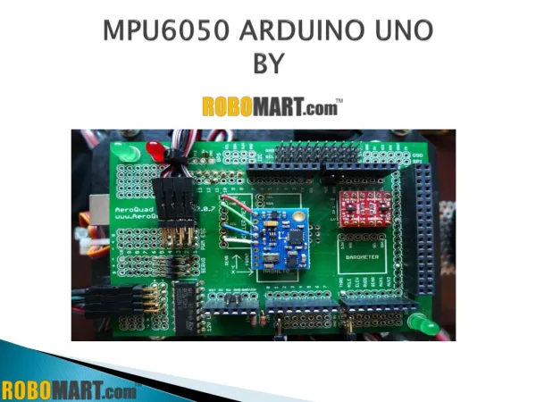
MSP430G2553 launchpad and MPU6050 Introduction. ---- Liqiang Du(EE MS) . MSP430 figure. MSP430 pin figure. MPU6050 module. VCC and GND for power supply: 3-5v. SCL and SDA for I2C communication with MSP430. XCL and XDA to connect magnetic sensor .

E N D
MSP430G2553 launchpad and MPU6050 Introduction ----Liqiang Du(EE MS)
MPU6050 module VCC and GND for power supply:3-5v SCL and SDA for I2C communication with MSP430 XCL and XDA to connect magnetic sensor
USCI I2C Mode Figure : I2C Bus Connection Diagram The two pull up resistor is necessary for I2C mode to work properly
I2C data transfer Figure : I2C Module Data Transfer The first byte after a START condition consists of a 7-bit slave address and the R/W bit. When R/W = 0, the master transmits data to a slave. When R/W = 1, the master receives data from a slave. The ACK bit is sent from the receiver after each byte on the 9th SCL clock.
I2C initialization code void Init_i2c(uint8_t devAddr) { UCB0CTL1 |= UCSWRST; // Enable SW reset UCB0CTL0 = UCMST + UCMODE_3 + UCSYNC; // I2C Master, synchronous mode UCB0CTL1 = UCSSEL_2 + UCSWRST; // Use SMCLK, keep SW reset UCB0BR0 = 10; // fSCL = 1Mhz/10 = ~100kHz UCB0BR1 = 0; P1SEL = BIT6 + BIT7; // Assign I2C pins to USCI_B0 P1SEL2 = BIT6 + BIT7; // Assign I2C pins to USCI_B0 UCB0I2CSA = devAddr; // Slave Address is 069h UCB0CTL1 &= ~UCSWRST; // **Initialize USCI state machine** IE2 |= UCB0RXIE + UCB0TXIE; // Enable RX and TX interrupt }
I2C Module Operating Modes Transmitter Master Receiver I2C Transmitter Slave Receiver
USCI UART Mode In asynchronous mode, the USCI_Ax modules connect the MSP430 to an external system via two external pins, UCAxRXD and UCAxTXD. UART mode is selected when the UCSYNC bit is cleared. In UART mode, the USCI transmits and receives characters at a bit rate asynchronous to another device. Timing for each character is based on the selected baud rate of the USCI. The transmit and receive functions use the same baud rate frequency.
UART initialization code void initUart(void) { UCA0CTL1 |= UCSSEL_2; // Use SMCLK UCA0BR0 = 104; // 1MHz 9600 UCA0BR1 = 0; // 1MHz 9600 UCA0MCTL = UCBRS0; // Modulation UCBRSx = 1 P1SEL = BIT1 + BIT2 ; // P1.1 = RXD, P1.2=TXD P1SEL2 = BIT1 + BIT2 ; // P1.1 = RXD, P1.2=TXD UCA0CTL1 &= ~UCSWRST; // **Initialize USCI state machine** IE2 |= UCA0TXIE; }
Shopping information MSP430G2 $9.99 https://estore.ti.com/MSP-EXP430G2-MSP430-LaunchPad-Value-Line-Development-kit-P2031.aspx MPU6050 $5.75 http://www.ebay.com/itm/MPU-6050-3-Axis-Accelerometer-Sensor-Gyroscope-6DOF-Module-3-3V-5V-For-Arduino-/161108492494?pt=LH_DefaultDomain_0&hash=item2582d080ce