Download
1 / 23
250 likes | 810 Vues
Engineering Design GE121 Isometric and Orthographic Sketching. Lecture 3A. Engineering Drawing vs. Sketching. Engineering Drawings Used as output of the design process to communicate the final design for production Precise lines and arcs, detailed, and almost always to scale

E N D
Engineering DesignGE121Isometric and Orthographic Sketching Lecture 3A
Engineering Drawing vs. Sketching • Engineering Drawings • Used as output of the design process to communicate the final design for production • Precise lines and arcs, detailed, and almost always to scale • Engineering Sketching • Used at conceptual stage of design • Freehand, general shapes and sizes, often just ballpark dimensions, not to a precise scale, but rather simply relative proportions • We will be primarily sketching
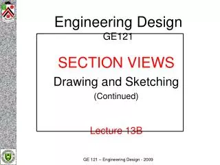
Isometric to Orthographic Orthographic Views are used extensively in engineering Often, they must be produced from a 3D object or possibly an existing Isometric drawing or sketch
Isometric to Orthographic • Hints for Orthographic Sketching • Identify the major features and overall dimensions • Use clean, crisp strokes • Do not use straightedges or scales when sketching • Start by drawing bounding boxes and a miter line, using construction lines • Align the views • Use light construction lines to locate vertices and edges • Only measure dimensions along primary axes • Map inclined and oblique faces between all three views • Follow the precedence of lines • Doublecheck to make sure there are no missing hidden or center lines • Darken all visible, hidden and center lines
Iso to Ortho Block in the 3 views using overall width, height and depth Front View first, then project height and width using construction lines Make sure depth is the same on Top and Right Views
Iso to Ortho Lightly block in major features in each view Place circles in views where they look round Begin darkening major features
Iso to Ortho Construction lines can be used to project location or size of one feature to another view A miter line can be used to project Depth dimensions
Iso to Ortho Finish adding all final lines Be sure to add all hidden and center lines Darken all final lines
Iso to Ortho Completed Sketch with construction lines erased
Orthographic to Isometric • Orthographic drawings are common in engineering. Visualizing or creating the Isometric View is a critical engineering skill
Orthographic to Isometric • Hints for Isometric Sketching • Identify major features and overall dimensions • Use clean, crisp strokes • Do not use straightedges or scales when sketching • Start by drawing a bounding box, using construction lines • Only measure dimensions along the primary axes • Do not directly transfer angles from a multiview to a pictorial • Use light construction lines to locate vertices and edges • Sketch faces roughly in this order: • Normal faces on the perimeter of the bounding box • Normal faces in the interior of the bounding box • Inclined faces • Oblique faces • Darken all object lines
Ortho to Iso • Set up Isometric Axis using 1 vertical line and 2 lines at 30 degrees from horizontal • Estimate the overall width height and depth of the object, and sketch the edges of a block that would completely enclose the object
Ortho to Iso • Sketch the outline of the front face using lines parallel and equal in length to the two previous height and width edges
Ortho to Iso • Sketch the outlines of the top and side faces using the same basic procedure as used for the front face • Begin sketching start/end points of major features
Ortho to Iso • Begin darkening major features as they are developed • Locate start/end points of additional and smaller features
Ortho to Iso • Locate and sketch start/end points for non-isometric lines such as the angled surface • Sketch and darken the non-isometric features
Ortho to Iso Completed Isometric Sketch with construction lines erased
Activity • Sketch a closed cell phone in Isometric View, and then in the 3 Standard Orthographic Views (Front, Top and Right Side) • If you complete early, attempt the same with the phone in the open position • Reference Images on the following slide for those without a cell phone to sketch