Download
1 / 24
260 likes | 816 Vues
Isometric and Orthographic Projections. Science and Technology Cycle II. Objectives. Understanding Graphic representations as a communication tool. Projections Orthographic. Isometric. Lines and elements. What can you learn about this object from this drawing?.

E N D
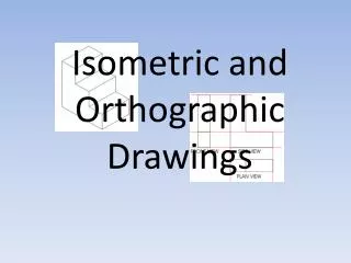
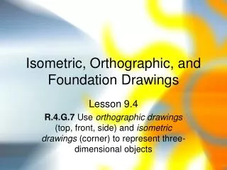
Isometric and Orthographic Projections Science and Technology Cycle II
Objectives • Understanding Graphic representations as a communication tool. • Projections • Orthographic. • Isometric. • Lines and elements.
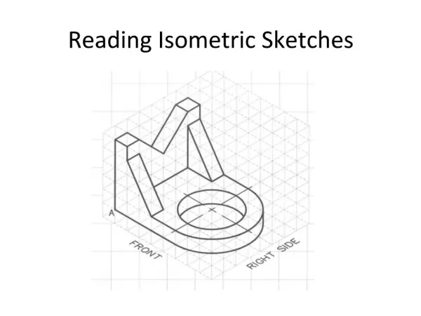
What can you learn about this object from this drawing? Could you build an accurate model only using this drawing? What is it’s size? What is it made of? What does the other side of it look like? Are there any moving parts? What is missing that you might need?
Three Basic Types of Technical Drawings • Freehand sketches • Instrument drawings • Computer drawings and models
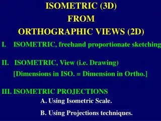
Introduction to Projections • Two Basic Categories • Presenting objects with 2-D media in 2-D or 3-D Orthographic and Isometric Pictorial
Projections: Four Basic Types Orthographic Isometric Oblique Perspective
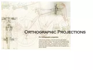
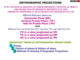
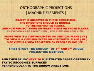
Orthographic Projections • The purpose of orthographic projections is to accurately represent object. • Accurately, means to make a drawing from which it is possible to manufacture or reproduce the object only using the drawing as a guide.
Sectional view Defining thePrincipal ViewsorOrthographic Views
Which Views to Present? General Guidelines • The Front View that is which is the most descriptive of object. • Has normally the longest dimension as the width (or length). • Most common combination of views is to use: Front, Top, and Side View, Which ever gives all information you need to understand the object. • Views other than the Principal Views are called Auxiliary Views.
Normally we use the front top or right side view only.The 4 other views only repeat what we already can see in the these views.These views can be seen by either physically or mentally rotating the object into the appropriate position to show the detail of the object visible form that view.
Width Depth Height Each view is constructed so that information (dimensions, and object edges, etc ..), are clearly related to the other views. Conventional Orthographic Views Top View Right Side View Top View Front View Right Side View Front View
Construction lines When a drawing is rendered, basic faint lines are drawn to provide a framework for the completion of the projection. Construction Lines Although not part of the object, these lines provide the framework to construct the drawing of the object.
Width Depth Height Dimension Lines display precise information about the size of the object. Dimension Lines Top View Right Side View Front View
Width Depth Height Object LinesRepresent features that are only visible in the current view. Object Lines Top View Right Side View Top View Front View Right Side View Front View
Hidden Linesrepresent features that cannot be seen in the current view. We show these unseen details, with dashed lines. Hidden lines ALL Hidden or internal details must be included.What does the inside of this block look like? Top View Right Side View Front View
Center lines represent symmetry and mark the center of circles, the axes of cylinders, and the axes of symmetrical parts, such as bolts. Center Lines Top View Again, though not part of the object, these lines are important elements of the objects dimension and construction. Right Side View Front View
A A A A Sectioning of a view The section line labeled A:A shows the arrows pointing in the direction to which you are observing the “cut” or section. Section Lines Are used to represent where the object is to be “cut” or sectioned to reveal interior details. This is used when other views may not adequately reveal information about the object. Sectional view A:A
Types of Lines in Orthographic Projections 10cm A A Construction lines - Basic faint lines which are drawn to provide a framework for the completion of the projection. Dimension Lines display precise information about the size of the object. Object Lines – represent visible features for an object. They are the darkest and most present. Hidden Lines – represent features that cannot be seen in the current view. They are as dark as the object lines. Center lines – represent symmetry and mark the center of circles, the axes of cylinders, and the axes of symmetrical parts, such as bolts Section Lines Are used to represent where the object is to be “cut” or sectioned to reveal interior details. This is used when other views may not adequately reveal information about the object.
Isometric View Review: Major views used in orthographic projections. 1. Object 2. Hidden 3. Center 4. Sectional
Height Depth Width