ORTHOGRAPHIC PROJECTIONS
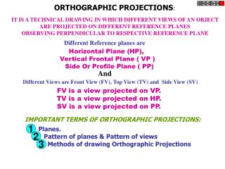
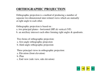
ORTHOGRAPHIC PROJECTIONS. Multiview orthographic projection is a method of drawing two or more views of an object on the RPs placed at right angles to each other. The word ‘ortho’ means perpendicular. In this projection, the projectors are perpendicular to the POP and parallel to each other.

ORTHOGRAPHIC PROJECTIONS
E N D
Presentation Transcript
ORTHOGRAPHIC PROJECTIONS Multiview orthographic projection is a method of drawing two or more views of an object on the RPs placed at right angles to each other. The word ‘ortho’ means perpendicular. In this projection, the projectors are perpendicular to the POP and parallel to each other. MULTIVIEW PROJECTION SYSTEM The three RPs required to obtain the views in multiview projections are the HP, the VP and the PP, Fig. 9.1. The HP and the VP make four quadrants. The position of an object in space can be determined by these quadrants, i.e., the object can be in the first quadrant or in the second quadrant or in the third quadrant or in the fourth quadrant. The line at which the HP and the VP meet is called horizontal reference line and denoted by XY. The line at which the HP (or the VP) and the PP meet is called the profile reference line and is denoted by X1Y1. After the views are obtained, the HP is rotated about XY in the clockwise direction to bring it in plane with the VP. The PP is rotated about X1Y1 away from the object.
ORTHOGRAPHIC VIEWS Front View When the observer looks at the object from the front, the view obtained is called the front view (FV) or Elevation. FV is seen on the VP. Top View When the observer looks at the object from above, the view obtained is called top view (TV) or plan. TV is seen on the HP. Side Views When the observer looks at the object from side, i.e., from his left-hand side or righthand side, the view obtained is called side view (SV). SV is seen on the PP. Left-Hand Side View When the observer views the object from his left-hand side, the view obtained is called left-hand side view (LHSV). Right Hand Side View When the observer views the object from his right-hand side, the view obtained is called as right-hand side view (RHSV). For longer objects of uniform cross section (e.g., long pipe, spline shaft, etc.), the SV is usually referred as end view. Bottom View When the observer looks to the object from below, the view obtained is called bottom view (BV) or bottom plan.
Rear View When the observer looks to the object from back, the view obtained is called rear view (RV) or back view or rear elevation. The FV, TV and either LHSV or RHSV are usually drawn in orthographic projection. The other views are added if they are extremely essential. METHODS OF MULTIVIEW PROJECTION First-angle Projection Method In first-angle projection, an object is placed in the first quadrant, i.e., above the HP and in front of the VP, Fig. 9.2(a). The observer looks at the object from the front (i.e., direction X) to obtain FV on the VP. Similarly, to get TV on the HP and LHSV on the PP, the observer looks at the object from the above (i.e., direction Y) and from the left side (i.e., direction Z) respectively. TV is placed below FV and LHSV is placed on the right side of FV. RHSV is placed on the left side of the FV.
Third-angle Projection Method In third-angle projection, an object is placed in the third quadrant, i.e., below the HP and behind the VP, Fig. 9.3(a). The RPs are rotated as in first-angle method, i.e., the HP in clockwise direction and the PP away from the object. Obviously, TV is placed above FV, LHSV on the left side of FV and RHSV on the right side of FV, Fig. 9.3(b).
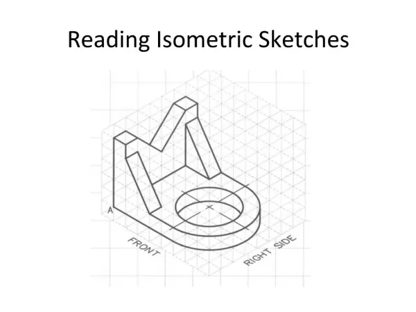
PROJECTING THE SVs The SVs are always placed alongside FV. They are obtained by drawing the projectors from FV and TV. ORTHOGRAPHIC VIEWS: SYSTEMATIC APPROACH Often, we are given with the pictorial (usually isometric) view of an object with the front direction of viewing, as shown in Fig. 9.4. The arrow marked X shows the direction through which the object is viewed to obtain FV. Note that this direction is perpendicular to the POP, i.e., the VP. Once the direction of viewing for FV is known, directions for other views, viz. TV, LHSV and RHSV can be easily decided. If the observer is facing the object, then his left-hand side and right-hand side will indicate the directions for LHSV and RHSV respectively. The direction of viewingfor TV will obviously be from top of the object.
To obtain the projections of various faces of an object, the following rules must be observed: • If a face is perpendicular to the direction of viewing, its true shape and size will be seen in that view. • If a face is parallel to the direction of viewing, it is seen as a line in that view. This view is called the line view or edge view. • If a face is inclined to the direction of viewing, its true shape and size will not be seen in any view. • If an edge of the object is perpendicular to the direction of viewing, its actual length will be seen in that view. • If an edge of the object is parallel to the direction of viewing, it is seen as a point in that view. This view is called point view. • If an edge of the object is inclined to the direction of viewing, its foreshortened length will be seen in that view. The foreshortened length is obtained by locating the end points of the edge.
Example 9.1 For the object shown in Fig. 9.6(a), draw FV, TV and LHSV. Solution The object has 10 faces, marked as A, B, C, ..., J. Except face G, all other faces are perpendicular faces. The face G is inclined. Therefore, all the faces other than face G will show their true shape and size in one of the orthographic views. The faces H, I and J are the right face, bottom face and rear face respectively and not visible. Refer Fig. 9.6(b). To obtain the FV, observer looks in the direction X. The faces which are perpendicular to the direction X will be seen in their true shape. The faces which are parallel to the direction X will be seen as edge views. Thus, faces A, C and E will be seen to their true shapes. The faces B, D, F and G will be seen as edge views. To obtain the TV, the observer looks in the direction Y. The face F will be seen in true shape. The face G will be seen foreshortened as it is inclined to the direction Y. The faces A, B, C, D, E, H and J will be seen as edge views. To obtain the LHSV, the observer looks in the direction Z. The faces B and D will be seen as their true shapes. The face G will be seen as foreshortened. The faces A, C, E, F, J and I will be seen as edge views. The three orthographic views are shown in Fig. 9.6(c). The LHSV is drawn on the right-hand- side of FV since we are following the first-angle method of projection.
Hidden Features The features of the object not seen in a particular view are called as hidden features. The hidden features, internal or external, are shown by drawing dashed lines for the edges (or extreme generators in case of cylindrical or conical features) forming the hidden feature in that particular view. Example 9.3 Draw the RHSV of the object of Example 9.1, Fig. 9.6(a). Solution It is clear that, in RHSV (i.e., the view in the direction W) the faces B, G and D will not be seen. However, as these are the hidden features, they are shown by dashed lines, Fig. 9.8.
Example 9.5 For the object shown in Fig. 9.10(a), draw FV (in direction X), TV, LHSV and RHSV. Solution With reference to Fig. 9.10(a), the faces that will be seen as true shapes, apparent shapes and hidden faces in different views are shown in the following table: Figure 9.10(b) shows the required four views. Please note carefully how hidden lines are drawn for the hidden faces.
Circular Features • The objects having circular faces (like cylindrical projections, holes, flanges, etc.) are characterized by the centrelines of the circular features. • Example 9.6 Draw FV, TV and RHSV of the object shown in Fig. 9.11(a). • Solution The object has a cylindrical projection on the front face and a vertical hole. Fig. 9.11(b) shows its three views. Note how centrelines are used to indicate the circular features. Also observe the dashed lines for the hole. • Precedence of Lines • Wherever visible line, hidden line and centrelines overlap, the following precedence rules should be observed: • A visible line has precedence over a hidden line and a centreline, i.e., visible line should only be drawn if it overlaps with a hidden line and/or centreline. • A hidden line has precedence over a centreline, i.e., a hidden line should only be drawn if it overlaps with a centreline. • If a visible line or a hidden line precedes a centreline, the ends of the centreline should be drawn to show its existance.
SECTIONAL VIEWS The internal hidden details of the object are shown in orthographic views by dashed lines. Obviously, the intensity of dashed lines in orthographic views depends on the complexity of internal structure of the object. Therefore, the general practice is to draw sectional views for complex objects in addition to or instead of simple orthographic views. A sectional view, as the name suggests, is obtained by taking the section of the object along a particular plane. An imaginary cutting plane is used to obtain the section of the object. Types of Cutting Planes and Their Representation A cutting plane is represented by a cutting plane line as explained in Chapter 2, Section 2.2.4. The cutting plane line indicates the line view of the cutting plane. The two ends of the cutting plane line are made slightly thicker and provided with arrows. The direction of the arrow indicates the direction of viewing of the object. In the first-angle method of projection, the direction of the arrows is toward the POP, i.e., toward XY (or X1Y1). Different types of section planes are explained in Fig. 9.25
Hatching of the Sections The surface created by cutting the object by a section plane is called as section. The section is indicated by drawing the hatching lines (section lines) within the sectioned area. The hatching lines are drawn at 45° to the principal outlines or the lines of symmetry of the section, Fig. 9.26. The spacing between hatching lines should be uniform and in proportion to the size of the section.
Various Sectional Views Figure 9.27(a) shows an object with the vertical cutting plane A–A, horizontal cutting plane B–B and profile cutting plane C–C marked on it. The corresponding sectional views are shown in Fig. 9.27(b)
Methods of Sectioning The sectioning should be made in such a way that all the complicated internal features of the object will be as clear as possible. The various methods of sectioning are explained below. Full Section The sectional view obtained after removing the front-half portion of an object through its centre is known as a full section, Fig. 9.28(a). Half SectionThe sectional view obtained after removing the front quarter portion by means of two cutting planes at right angles to each other is known as half section, Fig. 9.28(b).
Offset Section The sectional view obtained by a cutting plane in a zigzag way so as to reveal the maximum details of the object is known as an offset section, Fig. 9.29.
Revolved Section A revolved section is used to show the uniform shape of the object from end to end, Fig. 9.30. Removed Section A removed section is used to show the variable shape of the object from end to end, Fig. 9.31.
Aligned Section An aligned section is used to show the shape of features that do not align with the vertical and horizontal centrelines of the object, Fig. 9.32. Ribs and Other Standard Parts in Section When a cutting plane passes longitudinally through the centre of the ribs, spokes, webs or other standard parts, they are not shown sectional because it gives a wrong impression of the thickness or of the other details, Fig. 9.33.
Example 9.20 Draw the sectional FV, TV and SV of the object shown in Fig. 9.34(a). Solution The object is cut by cutting plane A– A as shown. This will give a full sectional view. As indicated by the direction of arrows on the cutting plane line, the FV will be sectional. The three views of the object, namely, sectional FV, TV and LHSV are shown in Fig. 9.34(b). The cutting plane line A– A is also shown in TV. As already explained, in the first-angle method, the arrows of cutting plane line are pointed toward XY, i.e., toward the other view. In the third-angle method, the arrows on the cutting plane line in one view (say TV) will be pointing away from other view (say FV).