ISOMETRIC PROJECTIONS
ISOMETRIC PROJECTIONS. ISOMETRIC PROJECTIONS.

ISOMETRIC PROJECTIONS
E N D
Presentation Transcript
ISOMETRIC PROJECTIONS • Interpretation of the shape of an object from a multi-view-drawing is difficult, without the knowledge of the principles of orthographic projections. Pictorial drawings are used to convey specific information to persons who cannot visualize an object from its views.
Isometric projection: Isometric projection is a pictorial projection of an object and it is a single view, in which all the three dimensions of an object are revealed. These projections are also used by the design engineers, in the design and development of new or complicated parts, the shape of which is difficult to understand from the multi-view drawings.
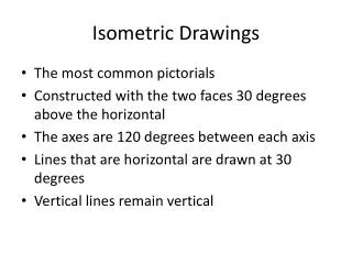
Principles of isometric projection: the Principles of isometric projection may be understood from the isometric projection of a cube. The isometric projection of a cube is obtained, when the line of sights parallel to its solid diagonal. If a cube is resting on one of its corners on H.P, with its solid diagonal perpendicular to V.P, the front view of the cube is its isometric projection. isometric means equal measurement, i.e., each of the three planes of the cube is equally fore-shortened. This projection is more appropriate in the case of small objects, but larger objects may appear to be unnatural. Perspective projection is used to represent larger objects. Isometric projection of a cube
Isometric scale: in isometric projection, the magnitudes of dimensions are reduced. Therefore, a special scale is required to draw the projection.
Isometric (view) drawing: An isometric view or drawing is similar in form to isometric projection, but actual measurements are transferred from the object to the axes, consequentially, the isometric view or drawing will be larger. it is customary to make an isometric view or drawing rather than isometric projection because, it is much easier to execute, as the size need not be reduced to the isometric scale each time. Also, isometric projection and isometric drawing appear alike. Difference between isometric projection and isometric drawing
Non- isometric lines: when an object contains lines (edges), which are not parallel to the isometric axes, these are known as non-isometric lines. These lines are drawn either by the box method or the offset method. (i) Box method: in this the object is imagined to be enclosed in a square/ rectangular box. This is done by enclosing the views in square/ rectangles. The box is first drawn in isometric and the object is located in it by marking its points of contact with the box. (ii) Off-set method: the method is further suited to objects made-up of a number of planes at different angles. The ends of the edges are located by dropping perpendiculars from each point to an isometric reference plane. The perpendiculars may be located on the drawing, as these are isometric lines and the respective magnitudes are transferred from the orthographic views. Isometric views with non-isometric lines
ISOMETRIC DIMENSIONING • If an isometric projection or drawing is to be dimensioned as a working drawing, it must be completely dimensioned. Extension lines, dimension lines and dimensions for the isometric projection or drawing must be placed in isometric plane of the faces. Use of centre lines for dimensioning Dimensioning lines and numerals on isometric projection
OFFSET METHOD Isometric projection of plane figures: Problem: figure a shows the projection of a pentagonal plane. Draw the isometric drawing of the plane, assuming the surface of the plane to be (i) parallel to V.P and (ii) parallel to H.P Isometric drawing of a pentagonal plane
Fig (a) shows the projection of a circle. Draw the isometric drawing of the circle. fig .(b) off-set or co-ordinate method- horizontal plane Fig .(c) off-set or co-ordinate method- vertical plane. Isometric drawing of a circle off-set method
Four-centre method: ISOMETRIC DRAWING OF A CIRCLE-FOUR CENTRE- METHOD NOTE:1. depending upon the orientation, part of the above construction may be used to draw the isometric drawing of a semi-circle. 2. The ellipse obtained by the four-centre method is an approximate one and for all practical purposes, it is generally acceptable.
Problem: Fig. a shows the orthographic views of an irregular pyramid. Draw isometric views Fog.c – Off-set method Fig.a Fig.b- box method
Isometrics of regular solids Problem: Draw isometric view of a hexagonal prism, with side of base 25 and axis 60 long. The prism is resting on its base on H.P, with an edge of the base parallel to V.P. use the box method
Problem: draw the isometric drawing of a cone of base diameter 30 and axis 45 long. Use the off-set method
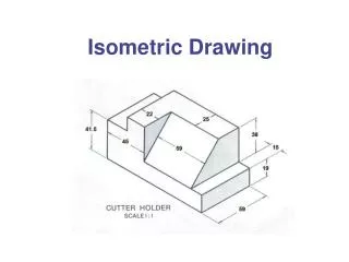
Isometrics of machine blocks Isometric from orthographic views