Download
1 / 33
390 likes | 707 Vues
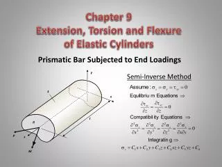
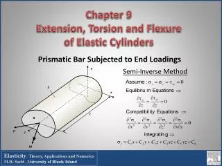
Chapter 9 Extension, Torsion and Flexure of Elastic Cylinders. Prismatic Bar Subjected to End Loadings. Semi-Inverse Method. Elasticity Theory, Applications and Numerics M.H. Sadd , University of Rhode Island. Extension of Cylinders. Assumptions

E N D
Chapter 9 Extension, Torsion and Flexure of Elastic Cylinders Prismatic Bar Subjected to End Loadings Semi-Inverse Method ElasticityTheory, Applications and NumericsM.H. Sadd , University of Rhode Island
Extension of Cylinders • Assumptions • Load Pzis applied at centroid of cross-section so no bending effects • Using Saint-Venant Principle, exact end tractions are replaced by statically equivalent uniform loading • Thus assume stress z is uniform over any cross-section throughout the solid Using stress results into Hooke’s law and combining with the strain-displacement relations gives Integrating and dropping rigid-body motion terms such that displacements vanish at origin ElasticityTheory, Applications and NumericsM.H. Sadd , University of Rhode Island
Torsion of Cylinders • Guided by Observations from Mechanics of Materials • projection of each section on x,y-plane rotates as rigid-body about central axis • amount of projected section rotation is linear function of axial coordinate • plane cross-sections will not remain plane after deformation thus leading to a warping displacement ElasticityTheory, Applications and NumericsM.H. Sadd , University of Rhode Island
y P' P S r O x R Torsional Deformations =angle of twist per unit length w =warping displacement Now must show assumed displacement form will satisfy all elasticity field equations ElasticityTheory, Applications and NumericsM.H. Sadd , University of Rhode Island
Stress Function Formulation Equilibrium Equations Compatibility Relation Introduce Prandtl Stress Function = (x,y) : Equilibrium will be identically satisfied and compatibility relation gives a Poisson equation that is amenable to several analytical solution techniques ElasticityTheory, Applications and NumericsM.H. Sadd , University of Rhode Island
Boundary ConditionsStress Function Formulation On Lateral Side: S n On End: R (z = constant) ElasticityTheory, Applications and NumericsM.H. Sadd , University of Rhode Island
Displacement Formulation Displacement component satisfies Laplace’s equation On Lateral Side: S On End: R ElasticityTheory, Applications and NumericsM.H. Sadd , University of Rhode Island
Formulation Comparison Displacement Formulation Stress Function Formulation Relatively Simple Governing Equation Very Simple Boundary Condition Very Simple Governing Equation Complicated Boundary Condition ElasticityTheory, Applications and NumericsM.H. Sadd , University of Rhode Island
Multiply Connected Cross-Sections Boundary conditions of zero tractions on all lateral surfaces apply to external boundary So and all internal boundaries S1, . . . Stress function will be a constant and displacement be specified as per (9.3.20) or (9.3.21) on each boundary Si, i = 0, 1, . . . where i are constants. Value of i may be arbitrarily chosen only on one boundary, commonly taken as zero on So . Constant stress function values on each interior boundary are found by requiring displacements wto be single-valued, expressed by where A1 is area enclosed by S1 Value of 1 on inner boundary S1 must therefore be chosen so that relation is satisfied. If cross-section has more than one hole, relation must be satisfied for each hole. Boundary conditions on cylinder ends will be satisfied, and resultant torque condition will give ElasticityTheory, Applications and NumericsM.H. Sadd , University of Rhode Island
Membrane Analogy Stress function equations are identical to those governing static deflection of an elastic membrane under uniform pressure. This creates an analogy between the two problems, and enables particular features from membrane problem to be used to aid solution of torsion problem. Generally used to providing insight into qualitative features and to aid in developing approximate solutions. Membrane Equations Torsion Equations Equations are same with: = z , p/N= 2 , T = 2V ElasticityTheory, Applications and NumericsM.H. Sadd , University of Rhode Island
Torsion Solutions Derived from Boundary Equation If boundary is expressed by relation f(x,y) = 0, this suggests possible simple solution scheme of expressing stress function as = K f(x,y) where K is arbitrary constant. Form satisfies boundary condition on S, and for some simple geometric shapes it will also satisfy the governing equation with appropriate choice of K. Unfortunately this is not a general solution method and works only for special cross-sections of simple geometry. ElasticityTheory, Applications and NumericsM.H. Sadd , University of Rhode Island
y b x a Example 9.1 Elliptical Section Look for Stress Function Solution satisfies boundary condition and will satisfy governing governing if Since governing equation and boundary condition are satisfied, we have found solution ElasticityTheory, Applications and NumericsM.H. Sadd , University of Rhode Island
Elliptical Section Results (Displacement Contours) (Stress Function Contours) Stress Field Displacement Field Loading Carrying Capacity Angle of Twist ElasticityTheory, Applications and NumericsM.H. Sadd , University of Rhode Island
T Elliptical Section Results3-D Warping Displacement Contours ElasticityTheory, Applications and NumericsM.H. Sadd , University of Rhode Island
Example 9.2 Equilateral Triangular Section For stress function try product form of each boundary line equation satisfies boundary condition and will satisfy governing governing if Since governing equation and boundary condition are satisfied, we have found solution ElasticityTheory, Applications and NumericsM.H. Sadd , University of Rhode Island
Equilateral Triangular Section Results (Stress Function Contours) (Displacement Contours) Stress Field Displacement Field Loading Carrying Capacity Angle of Twist ElasticityTheory, Applications and NumericsM.H. Sadd , University of Rhode Island
Additional Examples That Allow Simple Solution Using Boundary Equation Scheme y y a r = 2acos a . x r r = b x Circular Shaft with Circular Keyway (Exercise 9-22/23) Section with Higher Order Polynomial Boundary (Example 9-3) ElasticityTheory, Applications and NumericsM.H. Sadd , University of Rhode Island
Examples That Do Not Allow Simple Solution Using Boundary Equation Scheme y b a x Rectangular Section General Triangular Section ElasticityTheory, Applications and NumericsM.H. Sadd , University of Rhode Island
Example 9.4 Rectangular SectionFourier Method Solution y Previous boundary equation scheme will not create a stress function that satisfies the governing equation. Thus we must use a more fundamental solution technique - Fourier method. Thus look for stress function solution of the standard form b a x homogeneous solution must then satisfy Separation of Variables Method ElasticityTheory, Applications and NumericsM.H. Sadd , University of Rhode Island
Rectangular Section Results Stress Field Loading Carrying Capacity/Angle of Twist Displacement Field ElasticityTheory, Applications and NumericsM.H. Sadd , University of Rhode Island
Rectangular Section Results ElasticityTheory, Applications and NumericsM.H. Sadd , University of Rhode Island
Torsion of Thin Rectangular Sections (a<<b) Investigate results for special case of a very thin rectangle with a << b. Under conditions of b/a >> 1 y b a x Composite Sections Torsion of sections composed of thin rectangles. Neglecting local regions where rectangles are joined, we can use thin rectangular solution over each section. Stress function contours shown justify these assumptions. Thus load carrying torque for such composite section will be given by ElasticityTheory, Applications and NumericsM.H. Sadd , University of Rhode Island
Example 9.5 Hollow Elliptical Section For this case lines of constant shear stress coincide with both inner and outer boundaries, and so no stress will act on these lateral surfaces. Therefore, hollow section solution is found by simply removing inner core from solid solution. This gives same stress function and stress distribution in remaining material. Constant value of stress function on inner boundary is Load carrying capacity is determined by subtracting load carried by the removed inner cylinder from the torque relation for solid section Maximum stress still occurs at x = 0 and y = b ElasticityTheory, Applications and NumericsM.H. Sadd , University of Rhode Island
Tube Centerline a a A B t C Membrane o B A (Section aa) Hollow Thin-Walled Tube Sections With t<<1 implies little variation in membrane slope, and BCcan be approximated by a straight line. Since membrane slope equals resultant shear stress Load carrying relation: where A =section area, Ai= area enclosed by inner boundary, Ac= area enclosed by centerline Combining relations Angle of twist: where Sc= length of tube centerline ElasticityTheory, Applications and NumericsM.H. Sadd , University of Rhode Island
Cut Thin-Walled Tube Sections Cut Cut creates an open tube and produces significant changes to stress function, stress field and load carrying capacity. Open tube solution can be approximately determined using results from thin rectangular solution. Stresses for open and closed tubes can be compared and for identical applied torques, the following relation can be established (see Exercise 9-24) ElasticityTheory, Applications and NumericsM.H. Sadd , University of Rhode Island
x . r z y Torsion of Circular Shafts of Variable Diameter Displacement Assumption ur= uz = 0 u = u (r,z) Equilibrium Equations Stress Function Approach Boundary Condition Load Carrying Torque ElasticityTheory, Applications and NumericsM.H. Sadd , University of Rhode Island
r z 2 Conical Shaft Example 9-7 Stress Function Solution Displacement Stresses r is rigid-body rotation about z-axis and can be determined by specifying shaft rotation at specific z-location ElasticityTheory, Applications and NumericsM.H. Sadd , University of Rhode Island
Conical Shaft Example 9-7 = 30oComparison with Mechanics of Materials ElasticityTheory, Applications and NumericsM.H. Sadd , University of Rhode Island
Numerical FEA Torsion Solutions A (Stress Function Contours) (4224 Elements, 2193 Nodes) (Stress Function Contours) (4928 Elements, 2561 Nodes) (Stress Function Contours) (4624 Elements, 2430 Nodes) ElasticityTheory, Applications and NumericsM.H. Sadd , University of Rhode Island
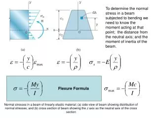
Flexure of Cylinders y Consider flexure of cantilever beam of arbitrary section with fixed end at z = 0 and transverse end loadings Px and Py at z = ℓ. Problem is solved in Saint-Venant sense, so only resultant end loadings Px and Py will be used to formulate boundary conditions at z = ℓ. S x Py ℓ . (xo,yo) R Px From general formulation , and motivated from strength of materials choose , where B and C are constants. Stresses xz and yzwill be determined to satisfy equilibrium and compatibility relations and all boundary conditions. z Remaining equilibrium equation will be identically satisfied if we introduce stress function F(x,y) such that ElasticityTheory, Applications and NumericsM.H. Sadd , University of Rhode Island
Flexure Formulation Remaining Beltrami-Michell Compatibility Relations Zero Loading Boundary Condition on Lateral Surface S Separate Stress Function F into Torsional Part and Flexural Part ElasticityTheory, Applications and NumericsM.H. Sadd , University of Rhode Island
Flexure Formulation General solution to where 2f = 0 Boundary Conditions on end z = ℓ where x, y and xy are the area moments of inertia of section R where J is the torsional rigidity – final relation determines angle of twist ElasticityTheory, Applications and NumericsM.H. Sadd , University of Rhode Island
Flexure Example - Circular Section with No Twist a z P x ℓ y Polar Coordinate Formulation Solution: Stress Solution: Strength of Materials: ElasticityTheory, Applications and NumericsM.H. Sadd , University of Rhode Island