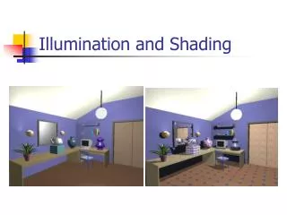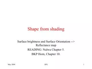
Lighting/Shading
Explore the fundamentals of lighting, shading, and reflection models in computer graphics. Learn about different light sources, reflection types, and the physics behind diffuse and specular reflections.

Lighting/Shading
E N D
Presentation Transcript
http://www.ugrad.cs.ubc.ca/~cs314/Vjan2013 University of British Columbia CPSC 314 Computer Graphics Jan-Apr 2013 Tamara Munzner Lighting/Shading
Correction: W2V vs. V2W slide 26, Viewing • MV2W=(MW2V)-1=R-1T-1
Recorrection: Perspective Derivation L/R sign error slide 91, Viewing z axis flip!
Reading for This Module • FCG Chapter 10 Surface Shading • FCG Section 8.2.4-8.2.5 • RB Chap Lighting
Geometry Database Model/View Transform. Perspective Transform. Lighting Clipping Frame- buffer Texturing Scan Conversion Depth Test Blending Rendering Pipeline
viewing transformation projection transformation modeling transformation viewport transformation Projective Rendering Pipeline OCS - object/model coordinate system WCS - world coordinate system VCS - viewing/camera/eye coordinate system CCS - clipping coordinate system NDCS - normalized device coordinate system DCS - device/display/screen coordinate system object world viewing O2W W2V V2C VCS WCS OCS clipping C2N CCS perspectivedivide normalized device N2D NDCS device DCS
Goal • simulate interaction of light and objects • fast: fake it! • approximate the look, ignore real physics • get the physics (more) right • BRDFs: Bidirectional Reflection Distribution Functions • local model: interaction of each object with light • global model: interaction of objects with each other
Photorealistic Illumination • transport of energy from light sources to surfaces & points • global includes direct and indirect illumination – more later [electricimage.com] Henrik Wann Jensen
Illumination in the Pipeline • local illumination • only models light arriving directly from light source • no interreflections or shadows • can be added through tricks, multiple rendering passes • light sources • simple shapes • materials • simple, non-physical reflection models
Light Sources • types of light sources • glLightfv(GL_LIGHT0,GL_POSITION,light[]) • directional/parallel lights • real-life example: sun • infinitely far source: homogeneous coord w=0 • point lights • same intensity in all directions • spot lights • limited set of directions: • point+direction+cutoff angle
Light Sources • area lights • light sources with a finite area • more realistic model of many light sources • not available with projective rendering pipeline (i.e., not available with OpenGL)
Light Sources • ambient lights • no identifiable source or direction • hack for replacing true global illumination • (diffuse interreflection: light bouncing off from other objects)
Ambient Light Sources • scene lit only with an ambient light source Light PositionNot Important Viewer PositionNot Important Surface AngleNot Important
Directional Light Sources • scene lit with directional and ambient light Light PositionNot Important Surface AngleImportant Viewer PositionNot Important
Point Light Sources • scene lit with ambient and point light source Light PositionImportant Viewer PositionImportant Surface AngleImportant
Light Sources • geometry: positions and directions • standard: world coordinate system • effect: lights fixed wrt world geometry • demo: http://www.xmission.com/~nate/tutors.html • alternative: camera coordinate system • effect: lights attached to camera (car headlights) • points and directions undergo normal model/view transformation • illumination calculations: camera coords
Types of Reflection • specular (a.k.a. mirror or regular) reflection causes light to propagate without scattering. • diffuse reflection sends light in all directions with equal energy. • mixed reflection is a weighted combination of specular and diffuse.
Types of Reflection • retro-reflection occurs when incident energy reflects in directions close to the incident direction, for a wide range of incident directions. • gloss is the property of a material surface that involves mixed reflection and is responsible for the mirror like appearance of rough surfaces.
Reflectance Distribution Model • most surfaces exhibit complex reflectances • vary with incident and reflected directions. • model with combination + + = specular + glossy + diffuse = reflectance distribution
shadow shadow Masked Light Surface Roughness • at a microscopic scale, all real surfaces are rough • cast shadows on themselves • “mask” reflected light:
Surface Roughness • notice another effect of roughness: • each “microfacet” is treated as a perfect mirror. • incident light reflected in different directions by different facets. • end result is mixed reflectance. • smoother surfaces are more specular or glossy. • random distribution of facet normals results in diffuse reflectance.
Physics of Diffuse Reflection • ideal diffuse reflection • very rough surface at the microscopic level • real-world example: chalk • microscopic variations mean incoming ray of light equally likely to be reflected in any direction over the hemisphere • what does the reflected intensity depend on?
Lambert’s Cosine Law • ideal diffuse surface reflection the energy reflected by a small portion of a surface from a light source in a given direction is proportional to the cosine of the angle between that direction and the surface normal • reflected intensity • independent of viewing direction • depends on surface orientation wrt light • often called Lambertian surfaces
Lambert’s Law intuitively: cross-sectional area of the “beam” intersecting an elementof surface area is smaller for greater angles with the normal.
l n Computing Diffuse Reflection • depends on angle of incidence: angle between surface normal and incoming light • Idiffuse = kd Ilightcos • in practice use vector arithmetic • Idiffuse = kd Ilight(n • l) • always normalize vectors used in lighting!!! • n, l should be unit vectors • scalar (B/W intensity) or 3-tuple or 4-tuple (color) • kd: diffuse coefficient, surface color • Ilight: incoming light intensity • Idiffuse: outgoing light intensity (for diffuse reflection)
Diffuse Lighting Examples • Lambertian sphere from several lighting angles: • need only consider angles from 0° to 90° • why? • demo: Brown exploratory on reflection • http://www.cs.brown.edu/exploratories/freeSoftware/repository/edu/brown/cs/exploratories/applets/reflection2D/reflection_2d_java_browser.html
Specular Highlights Michiel van de Panne
Physics of Specular Reflection • at the microscopic level a specular reflecting surface is very smooth • thus rays of light are likely to bounce off the microgeometry in a mirror-like fashion • the smoother the surface, the closer it becomes to a perfect mirror
Optics of Reflection • reflection follows Snell’s Law: • incoming ray and reflected ray lie in a plane with the surface normal • angle the reflected ray forms with surface normal equals angle formed by incoming ray and surface normal (l)ight = (r)eflection
Non-Ideal Specular Reflectance • Snell’s law applies to perfect mirror-like surfaces, but aside from mirrors (and chrome) few surfaces exhibit perfect specularity • how can we capture the “softer” reflections of surface that are glossy, not mirror-like? • one option: model the microgeometry of the surface and explicitly bounce rays off of it • or…
Empirical Approximation • we expect most reflected light to travel in direction predicted by Snell’s Law • but because of microscopic surface variations, some light may be reflected in a direction slightly off the ideal reflected ray • as angle from ideal reflected ray increases, we expect less light to be reflected
Empirical Approximation • angular falloff • how might we model this falloff?
Phong Lighting • most common lighting model in computer graphics • (Phong Bui-Tuong, 1975) v • nshiny: purely empirical constant, varies rate of falloff • ks: specular coefficient, highlight color • no physical basis, works ok in practice
Phong Lighting: The nshinyTerm • Phong reflectance term drops off with divergence of viewing angle from ideal reflected ray • what does this term control, visually? Viewing angle – reflected angle
Phong Examples varying l varying nshiny
Calculating Phong Lighting • compute cosine term of Phong lighting with vectors • v: unit vector towards viewer/eye • r: ideal reflectance direction (unit vector) • ks: specular component • highlight color • Ilight: incoming light intensity • how to efficiently calculate r ? v
Calculating RVector P = N cos q |L| |N| projection of L onto N P = N cos q L, N are unit length P = N ( N · L ) N P L q
Calculating RVector P = N cos q |L| |N| projection of L onto N P = N cos q L, N are unit length P = N ( N · L ) 2 P = R + L 2 P – L = R 2 (N ( N · L )) - L = R L P N P L R q
Phong Lighting Model • combine ambient, diffuse, specular components • commonly called Phong lighting • once per light • once per color component • reminder: normalize your vectors when calculating! • normalize all vectors: n,l,r,v
Blinn-Phong Model • variation with better physical interpretation • Jim Blinn, 1977 • h: halfway vector • h must also be explicitly normalized: h / |h| • highlight occurs when h near n n h v l
Light Source Falloff • quadratic falloff • brightness of objects depends on power per unit area that hits the object • the power per unit area for a point or spot light decreases quadratically with distance Area 4r2 Area 4(2r)2
Light Source Falloff • non-quadratic falloff • many systems allow for other falloffs • allows for faking effect of area light sources • OpenGL / graphics hardware • Io: intensity of light source • x: object point • r: distance of light from x
Lighting Review • lighting models • ambient • normals don’t matter • Lambert/diffuse • angle between surface normal and light • Phong/specular • surface normal, light, and viewpoint
Lighting in OpenGL • light source: amount of RGB light emitted • value represents percentage of full intensitye.g., (1.0,0.5,0.5) • every light source emits ambient, diffuse, and specular light • materials: amount of RGB light reflected • value represents percentage reflectede.g., (0.0,1.0,0.5) • interaction: multiply components • red light (1,0,0) x green surface (0,1,0) = black (0,0,0)
Lighting in OpenGL glLightfv(GL_LIGHT0, GL_AMBIENT, amb_light_rgba ); glLightfv(GL_LIGHT0, GL_DIFFUSE, dif_light_rgba ); glLightfv(GL_LIGHT0, GL_SPECULAR, spec_light_rgba ); glLightfv(GL_LIGHT0, GL_POSITION, position); glEnable(GL_LIGHT0); glMaterialfv( GL_FRONT, GL_AMBIENT, ambient_rgba ); glMaterialfv( GL_FRONT, GL_DIFFUSE, diffuse_rgba ); glMaterialfv( GL_FRONT, GL_SPECULAR, specular_rgba ); glMaterialfv( GL_FRONT, GL_SHININESS, n ); • warning: glMaterial is expensive and tricky • use cheap and simple glColor when possible • see OpenGL Pitfall #14 from Kilgard’s list http://www.opengl.org/resources/features/KilgardTechniques/oglpitfall/