Download
1 / 31
310 likes | 499 Vues
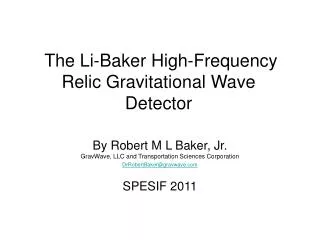
The Li-Baker High-Frequency Relic Gravitational Wave Detector. By Robert M L Baker, Jr. GravWave, LLC and Transportation Sciences Corporation DrRobertBaker@gravwave.com SPESIF 2011. Based In Part on the Following Manuscript.

E N D
The Li-Baker High-Frequency Relic Gravitational Wave Detector By Robert M L Baker, Jr.GravWave, LLC and Transportation Sciences Corporation DrRobertBaker@gravwave.com SPESIF 2011
Based In Part on the Following Manuscript “A new theoretical technique for the measurement of high-frequency relic gravitational waves” by R. Clive Woods, Robert M L Baker, Jr., Fangyu Li, Gary V. Stephenson, Eric W. Davis and Andrew W. Beckwith http://www.gravwave.com/docs/Theoretical%20technique%20for%20the%20measurement%20of%20HFGWs%20V3.pdf
INTRODUCTION • The measurement of High-Frequency Relic Gravitational Waves or HFRGWs could provide important information on the origin and development of our Universe. • There have been three instruments built to detect and measure HFRGWs, but so far none of them has the required detection sensitivity. • This lecture describes another detector, based on a new measurement technique, as referenced in the theoretical-physics literature, called Li-Baker detector. • Sensitivity as well as operational concerns, especially background noise, are discussed. • The potential for useful HFRGW measurement is theoretically confirmed.
What the Li-Baker Detector is Expected to Measure • The maximal signal and peak of HFRGWs expected from the beginning of our Universe, the “Big Bang,” by the quintessential inflationary models (Brustein, Gasperini, Giovannini and Veneziano 1995, Buonanno, Maggiore and Ungarelli 1997, de Vega, Mittelbrünn and Sanchez 1999, Giovannini 1999, Grishchuk 1999 and Beckwith 2009) and some string cosmology scenarios (Infante and Sanchez 1999, Mosquera and Gonzalez 2001, Bisnovatyi-Kogan and Rudenko 2004), may be localized in the gigahertz band near 10 GHz. • Their dimensionless spacetime strain (m/m), h, vary from up to ~ 10-30 to ~ 10-34 . Low-frequency gravitational wave detectors such as LIGO, which are based on interferometers, cannot detect HFRGWs (Shawhan 2004). • A frequency scan could reveal other HFRGW effects of interest in the early universe at a variety of HFRGW base frequencies other than 10 GHz.
Predicted relic gravitational wave energy density Ωg was a function of frequency (slide 6, Grishchuk 2007) and Hubble parameter n
HFRGW Detectors Already Built Three such detectors have been built (Garcia-Cuadrado 2009), utilizing different measurement techniques. And others proposed, for example by the Russians. They are promising for future detection of HFRGWs having frequencies above 100 kHz (the definition of high-frequency gravitational waves or HFGWs by Douglass and Braginsky 1979), but their sensitivities are many orders of magnitude less than that required to detect and measure the HFRGWs so far theorized. • The following slide shows the Birmingham HFGW detector that measures changes in the polarization state of a microwave beam (indicating the presence of a GW) moving in a waveguide about one meter across. It is expected to be sensitive to HFRGWs having spacetime strains of h ~2 ×10-13.
Additional Existing HFRGW Detectors The second of these alternate detectors was built by the INFN Genoa, Italy. It is a resonant HFRGW detector, comprising two coupled, superconducting, spherical, harmonic oscillators a few centimeters in diameter. The oscillators are designed to have (when uncoupled) almost equal resonant frequencies. In theory, the system is expected to have a sensitivity to HFRGWs with intensities of about h~ 2×10-17with an expectation to reach a sensitivity of ~ 2 ×10-20. Details concerning the present characteristics and future potential of this detector, especially its frequency bands, can be found in Bernard, Gemme and Parodi 2001, Chincarini and Gemme 2003, and Ballantini et al. 2005. As of this date, however, there is no further development of the INFN Genoa HFRGW detector. The third alternate detector is the Kawamura100 MHz HFRGW detector, which has been built by the Astronomical Observatory of Japan. It comprises two synchronous interferometers exhibiting arms lengths of 75 cm. Its sensitivity is h ≈ 10-16and its other characteristics can be found in Nishizawa et al. 2008.
Other HFRGW Detection Techniques Another HFRGW detector, under development by the Russians (Mensky 1975; Mensky and Rudenko 2009), involves the detection of gravitational waves by their action on an electromagnetic wave in a closed waveguide or resonator. Krauss, Scott and Meyer (2010) suggest that: “… primordial (relic) gravitational waves also leave indirect signatures that might show up in CMB (Cosmic Microwave Background) maps.” They suggest the use of thousands of new detectors (as many as 50,000) to obtain the required sensitivity.
Publications Presenting the Li-Effect or Li-Theory Fangyu Li ‘s new theory, upon which the Li-Baker Detector is based, was first published in 1992 and subsequently aspects of it were published in the following prominent, well-respected and often cited, peer-review journals: Physical Review D International Journal of Modern Physics B The European Physical Journal C International Journal of Modern Physics D The Li theory was scrutinized by Valentine Rudenko and Nikolai Kolosnitsyn of the Sternberg Astronomical Institute of Moscow State University in 2010.
Details of the Li Effect The Li Effect is very different from the well-known classical (inverse) Gertsenshtein (1962) effect. With the Li effect, a gravitational wave transfers energy to a separately generated electromagnetic (EM) wave in the presence of a static magnetic field. That EM wave, formed as a Gaussian beam (GB), has the same frequency as the GW and moves in the same direction. This is the “synchro-resonance condition,” in which the EM and GW waves are synchronized. It is unlike the Gertsenshtein effect, where there is no input EM wave that must be synchronized to the incoming gravitational wave. The result of the intersection of the parallel and superimposed EM and GW beams, according to the Li effect, is new EM photons moving off in a direction (both ways on the x-axis) perpendicular to the directions of the beams (GB and HFRGWs) on the z-axis and of the magnetic field (on the y-axis), as exhibited in a following slide. These photons signal the presence of HFGWs and are termed a “perturbative photon flux,” or PPF.
Li-effect detection photons directed to locations at both ends of the x-axis that are less affected by noise
Theory of Operation 1. A Gaussian microwave beam or GB (focused, with minimal side lobes) and off-the-shelf microwave absorbers for effectively eliminating diffracted waves at the transmitter horn’s edges (“out of sight” of the microwave receivers shown in yellow and blue in slide 21) is aimed along the +z-axis at the same frequency as the intended HFGW signal to be detected . 2. A static magnetic field B (generated typically using superconductor magnets such as those found in a conventional MRI medical body scanner) and installed linearly along the z-axis, is directed (N to S) along the y-axis 3. Semi-paraboloid reflectors are situated back-to-back in the y-z plane to reflect the +x and –x moving PPF detection photons (on both sides of the y-z plane in the interaction volume) to the microwave receivers. Alternatively, microwave lenses could be located outside of GB to focus the detection photons at the microwave receivers (slide 31).
Theory of Operation Continued 4. High-sensitivity, shielded microwave receivers are located at each end of the x-axis and below the GB entrance aperture to the Interaction Volume. Possible microwave receivers include an off-the-shelf microwave horn plus HEMT (High Electron Mobility Transistor) receiver; Rydberg Atom Cavity Detector (Yamamoto, et al. 2001) and single-photon detectors (Buller and Collins 2010). Of these, the HEMT receiver is recommended because of its off-the-shelf availability. 5. A high-vacuum system able to evacuate the chamber from 10-6to 10–11Torr (nominally about 7.5 ×10⁻⁷Torr) is utilized. This is well within the state of the art, utilizing multi-stage pumping, and is a convenient choice. Utilized to essentially eliminate GB scattering. • 6. A cooling system is selected so that the temperature T satisfies kBT<< ћω, where kB is Boltzmann’s constant and T<< ћω/kB≈3K for detection at 10 GHz. This condition is satisfied by the target temperature for the detector enclosure T< 480mK, which can be conveniently obtained using a common helium-dilution refrigerator so very few thermal photons will be radiated at 10 GHz in the narrow bandwidth (as narrow as 0.001 Hz). According a study accomplished at the University of Western Australia “It is shown that this technology (new low noise microwave technology and ultra-cryogenic techniques.”
Sensitivity The intersection of the magnetic field and the GB defines the “interaction volume” where the detection photons or PPF are produced. The interaction volume for the present design is roughly cylindrical in shape, about 30 cm in length and 9 cm across. In order to compute the sensitivity, that is the number of detection photons (PPF) produced per second for a given amplitude HFGW, we will utilize equation (7) of the analyses in Baker, Woods and Li (2006), which is a simplification of equation (59) in Li, et al. (2008), nx(1)= (1/μ0ћ ωe) AByψ0δs(1) where nx(1) is the number of x-directed detection photons per second produced in the interaction volume (defined by the intersection of the Gaussian beam and the magnetic field) , ћ = Planck’s reduced constant, ωe= angular frequency of the EM (= 2πνe), νe= frequency of the EM, A= the amplitude of the HFGW (dimensionless strain of spacetime variation with time), By= y-component of the magnetic field, ψ0= electrical field of the EM Gaussian beam or GB and δs is the cross-sectional area of the EM Gaussian beam and magnetic field interaction volume. For a proof-of-concept experiment, the neck of the GB is 20 cm out along the z-axis from the transmitter; the radius of the GB at its waist, W, is (λez/π)1/2 = (3 ×20/π)1/2 = 4.4 cm.
Standard quantum limit (SQL) -a result of the Heisenberg uncertainty principle There is another possible concern here: Stephenson (2009) concluded that a HFRGW intensity of hdet= 1.8×10–37m/m (strain in the fabric of space-time whose amplitude is A) represents the lowest possible GW strain variation detectable by each RF receiver in the Li-Baker HFGW detector. This limit is called “quantum back-action” or standard quantum limit (SQL) and is a result of the Heisenberg uncertainty principle. This sensitivity limit might be mitigated, however, by a “quantum-enhanced measurements using machine learning …” technique as discussed by Hentschel and Sanders (2010) and more specifically applied to optical interferometry as discussed by Steinberg (2010). An additional (1/√2) factor increase in maximum sensitivity applies if the separate outputs from the two RF receivers are averaged, rather than used independently for false alarm reduction, resulting in a minimum hdet = 1.2×10–37. Because the predicted best sensitivity of the Li-Baker detector in its currently proposed configuration is A = 10–30m/m, these results confirm that the Li-Baker detector is photon-signal-limited, not quantum-noise-limited; that is, the SQL is so low that a properly designed Li-Baker detector can have sufficient sensitivity to observe HFRGW of amplitude A ≈10–30m/m.
Scattering in the GB interaction volume We utilize the scattered intensity, I, from a molecule with incident intensity Io as given by (Nave 2009) I = Io (8π4 α2/λ4R2)(1 + cos2θ) where α is the atomic polarizability expressed as a polarization volume (where the induced electric dipole moment of the molecule is given by 4πεoαE), θ is the scattering angle, and R is the distance from particle to detector. Note that the scattering is not isotropic (there is a θ-dependence) but in the present case, θ= 90°so the ratio of incident to scattered photon intensity is given by . The polarizability is α≈1.1 ×10⁻³⁰m3from Robb (1974) so the scattering intensity ratio is 1.2 ×10-49for each atom in the chamber. The volume of interaction is about 2000 cm3 (30 cm long and roughly 8 cm ×8 cm in area) so at a pressure reduced to its base value of 7.5 ×10⁻⁷Torr at temperature 480 mK, the number of molecules contained is about 3 ×10¹⁶, giving a total scattering intensity ratio of 3.49 ×10⁻³³. There are 1.51 ×1026 photons produced per second in the 103W, 10 GHz GB. Therefore, in 103s of observation time, the number of photons received from Rayleigh scattering in the interaction volume over one-thousand seconds is much less than 1, and again scattering will be negligible.
Side-view schematic of the Li-Baker HFGW detector, exhibiting microwave-absorbent walls comprising an anechoic chamber
Schematic of the multilayer metamaterial or MM absorbers and pyramid absorber/reflector absorbent mat. Pat. Pend. • 1 Incident • 2 1stmetamaterial (MM) • 3 transmitted • 4 typical MM layer • 6 conventional • microwave absorber • 8 reflected • 10 remaining • Also seals against outguessing from the pyramid absorbers • – so will not affect vacuum system • The incident ray can have almost any inclination: Service (2010)
Diffraction of GB (from Woods 2011) ndif = k2 ((d/2)2/(32 Ld2) )exp(-½k2 [d/2]2)(0.01) nGB where k = 2π νe/c (nominally, 209 rad/m at 10GHz), c being the speed of light, the diameter of the GB throat is d (~ 0.09 m for the nominal case, essentially 2W) and nGB is the GB photon flux (nominally, 1.51 × 1026 photons per second). We will assume a single bounce or wave reflection of this diffraction-noise wave from the detector walls. The diffraction photon-path distance, prior to reaching the receivers, is Ld(~1 m for the nominal case). The number of diffracted photons reaching a receiver per second nrdif = ndif [arl π Ld)] εab where εab is the wall absorption coefficient (e.g., for the nominal case with the absorbent mat, it would be 10-22) and ar = area of the square receiver horn or receiving surface (nominally, one HFRGW wavelength square or 9×10⁻⁴ m2).
Results The total Noise Equivalent Power or NEP is 1.02×10⁻²⁶ W and is Quantization and thermal noise limited at roughly 1×10-26to 2×10-27W for a temperature of 0.48K (total noise flux is 1.54×10⁻³ photons per second). If need be the receivers could be further cooled and shielded from noise by baffles in which the spherical BPF wave front if significant, can be reduced by baffle diffraction and the PPF focused by the reflectors passed through the baffle openings with less interaction with baffle edges and less diffraction. Given a signal that exhibits the nominal value of 99.2 s-1photons, one quarter of which is focused on each of the microwave receivers, which is 24.8 s-1 photons or 1.6×10⁻²²W, the signal-to-noise ratio for each receiver is better than 1500:1.
CONCLUSIONS Three HFGW detectors have previously been fabricated, but analyses of their sensitivity and the results provided herein suggest that for meaningful relic gravitational wave (HFRGW) detection, greater sensitivity than those instruments currently provide is necessary. The theoretical sensitivity of the Li-Baker HFGW detector studied herein, and based upon a different measurement technique than the other detectors, is predicted to be A= 10-30m/m at a frequency of 10 GHz. This detector design is not quantum-limited and theoretically exhibits sensitivity sufficient for useful relic gravitational wave detection. Utilization of magnetic-field pulsed modulation allows for reduction in some types of noise. Other noise effects can only be estimated based on the Li-Baker prototype detector tests, and some of the design and adjustments can only be finalized during prototype fabrication and testing. The detector can be built from off-the-shelf, readily available components and its research results would be complementary to the proposed low-frequency gravitational wave (LFGW) detectors, such as the Advanced LIGO, Russian Project OGRAN and the proposed Laser Interferometer Space Antenna or LISA.
Microwave Lens on Each Side of GB Gaussian Beam (GB) Vacuum / Cryogenic Containment Vessel Signal PPF Z Signal PPF N magnetic pole Microwave Receiver - Detector #2 Microwave Receiver - Detector #1 X S magnetic pole Y HFRGWs pole Microwave lenses can be fractal membranes or metamaterial. They are not in the GB Containment vessel includes the anechoic chamber and microwave-absorbent walls Microwave Lenses Outside of GB