Download
1 / 30
310 likes | 420 Vues
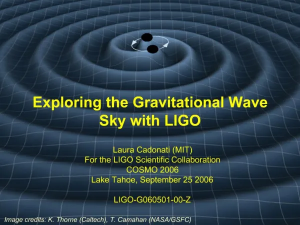
Optical Coating Development for the Advanced LIGO Gravitational Wave Antennas. Gregory Harry LIGO/MIT - On Behalf of the Coating Working Group -. University of Sannio at Benevento October 9, 2006 Benevento, Italy LIGO-G060506-00-R. Gravitational Wave Detection.

E N D
Optical Coating Development for the Advanced LIGO Gravitational Wave Antennas Gregory Harry LIGO/MIT - On Behalf of the Coating Working Group - University of Sannio at Benevento October 9, 2006 Benevento, Italy LIGO-G060506-00-R
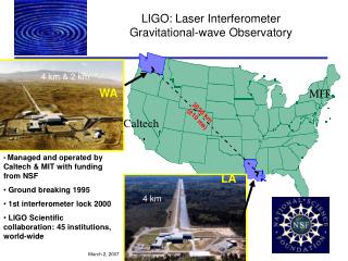
Gravitational Wave Detection • Gravitational waves predicted by Einstein • Accelerating masses create ripples in space-time • Need astronomical sized masses moving near • speed of light to get detectable effect LIGO • Laser Interferometer Gravitational-wave Observatory • Two 4 km and one 2 km long interferometers • Two sites in the US, Louisiana and Washington • Similar experiments in Italy, Germany, Japan • Whole optical path enclosed in vacuum • Sensitive to strains around 10-21 2
LIGO Sensitivity Measured sensitivity 6/2006 Seismic noise < 40 Hz Optics sit on multi-stage vibration isolation Laser shot noise > 200 Hz 10 W frequency and amplitude stabilized laser Thermal noise 40 Hz < f < 200 Hz Metal wire pendulum suspensions allow optic to move freely with gravity wave 3
Current LIGO Noise • Present noise at design value in all three interferometers • Some excess noise < 50 Hz • Noise reduction during breaks • Currently taking data • Will collect 1 years worth of • triple coincidence • Began in November 2005 • Extensive data analysis ongoing Hanford 4 K sensitivity • Neutron star inspirals 14.5 Mpc • 10 MO black hole inspirals to 50 Mpc • Stochastic background 7.5 10-6 • Crab pulsar e 2.8 10-5 • Sco X-1 e 3.0 10-7 4
Suspension power recycling mirror Advanced Configuration signal recycling mirror silica ribbon Improved coating Advanced LIGO • Proposed Sensitivity • Factor of 15 in strain improvement • Seismic isolation down to 10 Hz • 180 W of laser power • Larger optics with improved coating • Additional mirror for signal recycling 5
Advanced LIGO Sensitivity Initial LIGO Coating – Tantala/Silica Limits sensitivity 40 Hz – 400 Hz Thermooptic Noise high in same BW Need improved coating – including Brownian thermal noise, coating thermoelastic noise, and coating thermorefractive noise Brownian thermal noise limits at low frequency, even with reduced laser power/radiation pressure noise Thermal noise also limits narrowband sensitivity, sets floor Initial LIGO Coating Binary Neutron Star Inspiral 160 Mpc Binary Black Hole Inspiral 910 Mpc Neutron Star/Black Hole Inspiral 360 Mpc Stochastic Background 1.3 10-9 6
Measurement Techniques • Coating Thermal Noise • Q measuring on coated disks • Can test many candidate coatings • Thin – low freq – MIT, HWS, ERAU • Thick – high freq - Glasgow • Cantilevers – very low freq – LMA, Glasgow • Direct thermal noise • measurements at the TNI Thin Sample TNI Result of Tantala/Silica Coating Thick Sample • Optical Performance • Absorption measurements using photothermal common path interferometry (Stanford, LMA) • Developments with initial LIGO optics • High Scatter • High Absorption PCPI Setup 7
Initial LIGO Tantala/Silica Coating Coating Mechanical Loss Layers Materials Loss Angle 30al/4 SiO2 - l/4 Ta2O5 2.7 10-4 60 al/8 SiO2 - l/8 Ta2O5 2.7 10-4 2 al/4 SiO2 – l/4 Ta2O5 2.7 10-4 30 al/8 SiO2 – 3l/8 Ta2O5 3.8 10-4 30 a3l/8 SiO2 – l/8 Ta2O5 1.7 10-4 30 bl/4 SiO2 – l/4 Ta2O5 3.1 10-4 30 cl/4 SiO2 – l/4 Ta2O5 4.1 10-4 30 dl/4 SiO2 – l/4 Ta2O5 5.2 10-4 a LMA/Virgo, Lyon, France b MLD Technologies, Mountain View, CA c CSIRO Telecommunications and Industrial Physics, Sydney, Australia d Research-Electro Optics, Boulder, CO Direct Coating Thermal Noise Measurement No effect from from interfaces between layers nor substrate-coating Internal friction of materials seems to dominate, with tantala having higher mechanical loss Noticeable differences between vendors f – Ta2O5 (3.8 ± 0.2) 10-4 + f(1.1±0.5)10-9 f– SiO2 (1.0± 0.2) 10-4 + f(1.8±0.5)10-9 Tantala/Silica Coating Mechanical Loss 8
TiO2-doped Ta2O5 Titania-doped Tantala/Silica Coatings Examined titania as a dopant into tantala to try to lower mechanical loss f1 = (2.2±0.4)10-4 + f(1.2±0.6) 10-9 f2 = (1.6±0.1)10-4 + f(1.4±0.3) 10-9 f3 = (1.8±0.1)10-4 + f(-0.2±0.4)10-9 f4 = (1.8±0.2)10-4 + f(1.7±0.6) 10-9 f5 = (2.0±0.2)10-4 + f(0.1±0.4) 10-9 G. M. Harry et al, Submitted to Classical and Quantum Gravity, gr-qc/0610004 TNI Noise from Titania doped Tantala/Silica Young’s modulus and index of refraction nearly unchanged from undoped tantala Optical absorption acceptable ≈ 0.5 ppm 9
Advanced LIGO Baseline Coating Advanced LIGO Baseline Titania-doped Tantala/Silica Baseline Advanced LIGO Coating – Titania doped Tantala/Silica Still not limited by quantum noise Limits sensitivity 40 Hz – 200 Hz Thermo-optic Noise high in same BW Narrowband high frequency configurations still limited by coating thermal noise Acceptable impedance match with substrate Acceptable coating thickness Binary Neutron Star Inspiral 175 Mpc Binary Black Hole Inspiral 975 Mpc Neutron Star/Black Hole Inspiral 390 Mpc Stochastic Background 1.2 10-9 10
Advanced LIGO Backup Coating Silica doped Titania/Silica -Backup Coating- Ratio(Si:Ti) Absorption Index Y Run 1 50/50 1.5 ppm 2.15 87 GPa Run 2 65/35 0.5 ppm 1.85 73 GPa • Thick Sample – Run 1 • = (2.4 +/- 0.9) 10-4 Thin Sample Run 1* f = (3.1 +/- 0.2) 10-4 Run 2 f = (1.9 +/- 0.3) 10-4 • Low Young’s Modulus • Low Index (Thicker Coating) • Good Mechanical Loss • Good Optical Absorption Binary Neutron Star Inspiral 175 Mpc Binary Black Hole Inspiral 960 Mpc Neutron Star/Black Hole Inspiral 385 Mpc Stochastic Background 1.2 10-9 11
Other Coatings Attempted • Niobia/Silica – high mechanical loss, unknown optical absorption • Hafnia/Silica – poor adhesion, poor absorption, never measured for f • Alumina/Silica – thick coating, good mechanically and optically • Dual ion beam (oxygen) – interesting, shows differences in mechanical loss between masks but not improvement over baseline • Oxygen poor – high mechanical loss, waiting on annealing in nitrogen atmosphere, high absorption • Xenon ion beam – increased mechanical loss • Lutetium doped Tantala/Silica – no improvement in mechanical loss • Differing annealings – inconclusive, no major improvements, absorption issues • Effect of substrate polishing – no effect on mechanical loss • Most of these do not have Young’s modulus measurements or optical absorption 12
New Coating Materials Ozone annealing – improve stoichiometry Neon ion beam – xenon made things worse Alumina as dopant into Ta, Ti, or Si Tungsten dopant into Ta (and Ti, Nb, Hf, etc) Zirconia Hafnia – solve adhesion problem Cobalt as dopant – only layers near substrate Dopants:high index-high index Hf-Ta Nb-Ti Hf-Nb, etc Trinary alloys Ta-Ti-Si Ni-Ta-Ti-Zr-Hf-Si-Al Si-O-N Other nitrides 13
Advanced LIGO with High Thermorefractive Noise Thermo-optic Noise • Coating thermorefractive (b=dn/dT) and coating thermoelastic noise (a=dL/dT) are coherent noise sources • Combined noise – Thermo-optic Noise • Best number in literature indicates very high thermorefractive noise from tantala b = 1.2 10-4 • Thermo-optic noise at this level ruled out by TNI upper limits • Almost certainly wrong, but what is the right value? • Significant reduction in sensitivity Binary Neutron Star Inspiral 150 Mpc Binary Black Hole Inspiral 910 Mpc Neutron Star/Black Hole Inspiral 340 Mpc Stochastic Background 1.4 10-9 14
dn/dT Measurement • Thermorefractive(b=dn/dT)/coating • thermoelastic noise(a=dL/dT) noise correlated • b from literature (Inci J Phys D:Appl Phys, 37 (2004) 3151) • 1.2 X 10⁻⁴ • This value makes combined noise an AdvLIGO • limiting noise source • Limits from TNI encouraging that b is lower • Need a good value for tantala, titania doped • tantala, and other promising coatings • Experiment at Embry-Riddle • Aeronautical University • Measure change in reflectivity • versus temperature • Use green He-Ne laser at 45 degrees • 100 C change in temperature enough • to verify/rule out Inci result for tantala 15
Young’s Modulus of Coatings • Coating Young’s modulus just as important to thermal noise as mechanical loss • Acoustic reflection technique used to measure coating impedance in collaboration with Stanford (I Wygant) • MLD alumina/tantala 176 +/- 1.1 GPa • MLD alumina/tantala 167 +/- 1.3 GPa • MLD silica/tantala 91 +/- 7.0 GPa • WP alumina/tantala 156 +/- 20 GPa • Uses assumed values for material densities • Infer material Young’s moduli • YTa2O5 = 140 +/- 30 GPa • YAl2O3 = 210 +/- 30 GPa (MLD) • YAl2O3 = 170 +/- 30 GPa (WP) • Large errors problematic when propagated Fit of Young’s Modulus of Tantala/Alumina 16
Study of Materials • Measurements being made at Glasgow, Southern, and Caltech • Titania concentrations in titania-doped tantala consistent – LMA/SU/UG • Southern finding titania using XRF, XANES, EXAFS • Plans for AFM and GIXAFS at Southern • Hopes for further insights into coating makeup and structure from studying contaminants X-Ray Florescence Results from Southern University / CAMD Electron Energy Loss Spectroscopy results from Glasgow 17
Modeling and Molecular Cause of Mechanical Loss Goal: A description of mechanical loss in thin film amorphous oxides from basic principles • Molecular dynamics calculations beginning at University of • Florida • Have a working semi-empirical model of loss in fused silica • Frequency dependence from two level systems • Surface loss as observed phenomenon • Develop full molecular description of silica loss • Surface loss caused by two member rings • Generalize to other amorphous oxides • Analogous two level systems • Mechanical loss data at different temperatures • Tantala/Silica T>300 C • Ti doped Tantala/Silica T<300 C • With frequency dependence, start to fit to modeling 18
Thermal Noise inThird Generation • Crucial to improve beyond Advanced LIGO levels to exploit QND, very low frequency seismic isolation, improved topologies, high laser power, etc • Short cavities as reflectors • Khalili (Phys Lett A 334 (2005) 67) • Significant added complexity • No experimental work so far • Corner reflectors • Braginsky and Vyatchanin (Phys Lett A 324 (2004) 345) • Practical concerns (scatter, finess, angular stability, etc) • Experiment at Australian National University -99.89% reflectivity observed • Lower temperatures • Need to restudy all materials as properties change • Some preliminary experimental work • New substrate materials (sapphire, silicon, etc) • Will require new coatings • Possibly dopants added to substrates • Change in beam shapes • Mesa beams – better averaging of thermal fluctuations • Higher order modes • General theory from O’Shaughnessy/Lovelace • Experiments at Caltech 19
Thermal Lensing • Absorption of optical power in mirrors causes heating • Most absorption in coatings because of higher power in the Fabry-Perot cavities • Heating of optic causes physical distortions and changes in index of refraction • Optical path length changes distorts wavefront • Causes poor contrast defect, ultimately increased shot noise and poor sensitivity • Thermal lensing can be corrected by adding heat to cold parts of optic • Use ring heaters or CO2 lasers • Limit to how much heat can be provided • Inhomogeneous absorption requires scanning laser system • Increase in rad pressure noise • Complicated controls • Need coatings to have absorption ≤ 0.5 ppm and homogeneous 20
Excess Absorption at Hanford • Input optics curved to match recycling mirror curvature at 8 W • Point design assumes a value for absorption • Found best matching at 2.5 W • Additional absorption causes excess thermal lensing • Excess absorption has to be in recycling cavity optic • Input mirrors or beamsplitter Other interferometers (2 K at Hanford and 4 K at Livingston) found to have much less absorption than expected Sideband Recycling Gain LIGO 4K Hanford IFO 21
Initial LIGO Thermal Compensation Design • 8 W CO2 laser directly projected onto mirrors • Ring heater not used to minimize installation time in vacuum • Scanning laser not used to avoid Shack-Hartmann sensors and radiation pressure issues • Different masks used to compensate for high or low absorption • Laser power controlled by acousto-optic modulator (H2) and rotating polarization plate (H1, L1) • Power controlled by feedback from IFO channels 22
Bench Tests of H1:ITMx • H1:ITMx shipped to Caltech immediately after removal • Absorption measured using photothermal common-path interferometry • Background < 1 ppm • Significant outliers with absorption > 40 ppm • Dust source of absorption? • Soot from brush fire in 2000? • Attracted by charged surface? • Insufficient cleaning and handling procedures? 23
Conclusions • Coating thermal noise limiting noise source in Advance LIGO’s most sensitive frequency band • Determined source of coating mechanical loss is internal friction in constituent materials • High index, typically tantala, is the biggest source of thermal noise • Doping a means of reducing mechanical loss • Titania doped into tantala • Silica doped in titania • Many other techniques tried to improve thermal noise, many still to be pursued • Thermo-optic noise a potential problem that is understudied • Need more information on coating Young’s moduli • Much work to be done with characterizing coating materials and developing thermal noise theory • New ideas for third generation only beginning to get attention • Absorption and scatter high in Initial LIGO • Both at levels that would not be acceptable in Advanced LIGO 24
Theory Sx(f) =d(1-s2)/(p w2)((1/(Yperp (1-s2))-2 s22Ypara/(Yperp2 (1-s2)(1-s1))) fperp+ Yparas2(1-2s)/(YperpY(1-s1)(1-s))(fpara-fperp)+Ypara(1+s)(1-2s)2/(Y2(1-s12)(1-s))fpara) • What we have • Complete theory of infinite mirror from Levin’s theorem • Anisotropic coatings including Young’s modulus, loss angles, and Poisson ratios • Relationship between total anisotropic coating parameters and isotropic individual material parameters • FEA models of finite mirror effects • Theory of coating thermoelastic loss • General theory of coatings and substrates, both Brownian and thermoelastic, for any beam shape for infinite mirrors • Optimization of coating thicknesses for thermal noise and reflectivity (see talk by V Galdi) • What we need • Empirical formula for finite mirror effects • Analytical theory of finite mirrors • Molecular level description of loss angles and other parameters • Complete optimization over thermal noise, reflectivity, absorption, scatter, etc. 25
Excess Absorption at Hanford • Three techniques used to determine source of excess absorption • Change in g factor • Thermal compensation power • Change in spot size • Fairly consistent result (assuming absorption in HR coating) • ITMx 26 ppm • IMTy 14 ppm • Design 1 ppm • Resulting changes • ITMx replaced • ITMy drag wiped in situ Spot size measurements: Data and technique 27
Absorption improvement at Hanford • ITMx replaced with spare optic • ITMy drag wiped in place • Both optics (ITMx and ITMy) show improved absorption • Both < 3 ppm • Power 6.8 W - mode cleaner • Shot noise at design level • 15 Mpc binary neutron star inspiral range 28
Thermal Compensation Upgrades and Challenges ITM Compensation Plates PRM ITM SRM • Initial LIGO compensation effective at 100 mW absorbed • Advanced LIGO expected to have 350 mW absorbed • Cleanliness and handling will be crucial • Need to keep absorption down • Potential improvements for advanced detectors • Graded absorption masks • Scanning laser system • Compensation plate in recycling cavity • Graded absorbing AR coating • DC readout, reducing requirements on RF sidebands • Challenges • Greater sensitivity • New materials – sapphire ~ 20 ppm/cm absorption • Compensation of arm cavities • Inhomogeneous absorption • Noise from CO2 laser 29
Advanced LIGO Thermal Compensation • Ring heaters simplest compensation system • Adds a lot of unnecessary heat • Could cause thermal expansion of other parts • Scanning laser system causes noise • Jumps in location cause step function changes in thermal expansion • Harmonics of jump frequency could be in-band • Could require feedback with Hartmann sensors or similar • Staring laser system works on Initial LIGO • Could require unique masks for each optic • Unique masks could be inappropriate as system is heating up • CO2 laser noise still a problem 30