RHIC optics for OSC
240 likes | 378 Vues
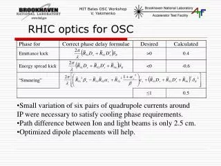
RHIC optics for OSC. Small variation of six pairs of quadrupole currents around IP were necessary to satisfy cooling phase requirements. Path difference between Ion and light beams is only 2.5 cm. Optimized dipole placements will help. Optical Stochastic Cooling for RHIC. Idea, Motivation,

RHIC optics for OSC
E N D
Presentation Transcript
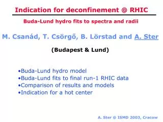
RHIC optics for OSC • Small variation of six pairs of quadrupole currents around IP were necessary to satisfy cooling phase requirements. • Path difference between Ion and light beams is only 2.5 cm. • Optimized dipole placements will help.
Optical Stochastic Cooling for RHIC • Idea, Motivation, • Numbers for beams of Gold, Protons @100GeV and 250GeV • Simulations, OSC and electron cooling • Components • OPA test at BNL
sample length ~10 cm sample length ~50 mm Basic idea Optical Stochastic Cooling Stochastic Cooling In practice time is amplifier limited • ~ 5 cm => ideal bandwidth limited cooling time t~2.5 hrs, practical >30 hrs • ~ 12 mm => bandwidth limited t~11 sec!, power limited cooling time t~1 hr with 16 W of optical power;
Why we need OSC if we have electron cooling Beam profile Cooling rate OSC OSC a.u. Electron cooling Electron cooling -4 -2 0 2 4 s 0 2 4 6 8 10 s Optical stochastic cooling can effectively reduce number of the particles in the beam tails. This will increase lifetime of the beam and reduce detectors background. Custom beam shaping might be possible. (Preliminary calculation of the beam distribution with Betacool)
Components of OSC • Pickup and kicker • Optical amplifier • RHIC lattice modification design • Diagnostics
Optimal wavelength • Wiggler period depends on the operating wavelength and beam energy • Period of the wiggler should be practical for the high field ~10T design • Longer wavelength require longer wigglers • Shorter wavelength would require high accuracy of the bypass optics tuning (fraction of the wavelength is required). • Optical amplifier should exist at operating wavelength with adequate bandwidth
ion beam p s i = p - s; kp = ks + ki s p Amplified signal Pump Laser Parametric Amplifier Nonlinear crystal CdGeAs2 d36= 236 pm/V pump = 5.3 mm (Doubled frequency, CO2 laser) signal = 12 mm PL = 20 MW/cm2 (damage threshold, conservative) l = 4 mm (e times gain length) 3 cm length crystal → intensity gain 3 105
Advantages Highest Nonlinear Coefficient of any known compound (d = 236 pm/V) 14 10K Long Wavelength IR Cut-off (17 microns) 1000 CdGeAs2 Large Birefringence allows ZnGeP2 100 Tl3AsSe3 for Broad Phase-Matching AgGaSe2 Range CdSe AgGaS2 10 Nonlinear Figure of Merit (d²/n³) Ag3SbS3, Ag3AsS3 Adequate Thermal LiIO3 LNbO3 Conductivity (.042 W/cmK) 1 for high power applications Disadvantages ADP 0.1 KDP Anisotropic Thermal Expansion SiO2 (a-axis 15x> c-axis), cracking 0.01 0 5 10 15 20 25 30 35 Transparency Range (Microns) Defect-related Absorption Loss CdGeAs2 has long been known as a promising nonlinear optical material for IR frequency conversion
Absorption Loss Mechanisms in CGA Primary limitation of CGA: defect-related absorption • All undoped CGA is p-type • high purity materials imply defects are probably intrinsic/native • intrinsic acceptors: VCd, CdGe, GeAs • intrinsic donors: VAs, GeCd, AsGe • p-type = more acceptors than donors • Thermally ionized shallow acceptors leave holes in upper valence band • Transitions from lower lying states result in 3 absorption features (intraband absorption) • Transitions from acceptor to donor states results in additional absorption (intercenter absorption)
Loss Reduction in CdGeAs2 • Minimize anti-site defect concentration • Exploit unique faceting mechanism to zone out absorbing defects • Compensate existing defects via doping • Add donors to ionize all acceptors • Create more intrinsic donor defects • Irradiate device crystals with fast electrons (5-10 MeV) • irradiation effects unstable above 200 deg. C • over-irradiation causes p- to n-type conversion • penetration depth limited to 1-2 mm
1W CW CO2 laser at 9.6mm transmit @ 5.3 absorb10.6 mm transmit @ 9.6 reflect 5.3 mm transmit @ 5.3 reflect 10.6 mm CO2 Oscillator 1MW @10 Hz Pockel cells Doubling crystal 200W CW CO2 laser 1W CW 9.6mm 100kW 200ns 10.6mm 100kW 10ns 10.6mm 20kW 10ns 5.3mm 2kW 10ns 9.6mm & 12 mm CdGeAs2 crystal Crystal based amplifier
OPA test at ATF • Basic parameters of the crystal • Bandwidth of the amplifier • Phase fidelity
Optical beam parameters for RHIC • 109 Gold ions beam is 1 ns long and radiate 8pJ with up to 10 MHz repletion rate at 12 mm wavelength (10% bandwidth) in a 3m long 10T wiggler (period 30 cm) • This light is amplified 2.105 times in a 3cm long CdGeAs2 crystal to the level of 1.6mJ or (1.6KW peak or up to 16W average power) • 50mJ, 2ns long doubled CO2 light at 5.3mm is planned as a pump source (50KW peak or up to 500W average power)
Basic parameters of the crystal Measurements of the angular dependence of the efficiency for second harmonic generation provides basic information about crystal
Bandwidth measurements 15MW/cm2and 5MW/cm2pump laser
Lattice Design Tune diagnostics RHIC lattice design Mode locked pump source Collaboration with FIAN CRDF proposal High field wigglers 10T in the proposal 15T state of the art Optical amplifier Gain length (done) Bandwidth (done) Phase fidelity (close) High average power handling Stabilized optical transport line Colors: Scientific research Engineering design Economical optimization Current state of OSC components
Conclusion on OPA • Extensive simulations of the optical parametric amplifier based on CdGeAs2 proved applicability to OSC • Test stand with two dedicated and one sharedtunable CO2 lasers completed • Basic properties of the CdGeAs2 crystal confirmed experimentally • Bandwidth of the OPA confirmed experimentally • Experiments for phase fidelity and operations at liquid N2 temperatures are in progress • Proposal to CDRF is submitted 2006-2009 to support pump souse research (Not funded)
OSC can be divided into 5 main components • Optical amplifier (Optical Parametric Amplifier (OPA): 3 cm long CdGeAs2 crystal, cooled to 77K for better thermal conductivity and transparency) • Pump source for OPA (mode locked CO or CO2 laser operating at 10 MHz with 200W output at 5.3micron) • RHIC lattice modification design • Diagnostics • Pair (per ring) of 10T 3 meter long wigglers and modified RHIC bending magnets (to allow wiggler light extraction)
Electron cooling: ion beam “heat” transferred to “cold” electron beam Limited by electron beam current Works over wide range of the ion beam energies Effective for the beam core and against IBS (faster cooling for the colder beam) Complimentary with OSC as it effective against IBS (main growth in RHIC) Requires expensive and challenging ERL and long solenoid EC was not demonstrated at high energies Stochastic Cooling: beam error signal is measured by a pickup, amplified by RF amplifier and corrected in the kicker Experiment on RHIC–Spring 2004 Works over wide range of the ion beam energies Limited by amplifier bandwidth ~5GHz Requires expensive RF amplifier Possibly can cool only tails of the RHIC beam Making sense of the different cooling techniques Optical SC: Same as SC, but at optical wavelength • Not limited by amplifier bandwidth ~3THz • Can cool whole RHIC beam in one hour with16W of optical power • Favors large amplitudes, can be adjusted for the different beam amplitudes • Greatly reduces requirements on electron current if used with EC • Works over limited ~5-10% range of the ion beam energies • Requires challenging RHIC lattice modifications • No experimental demonstration – period. Neither cooling was demonstrated for the bunched beam(Colors: Good,Bad)