Download
1 / 19
190 likes | 340 Vues
Mobile Test Bench for the LHC Cryogenic Instrumentation Crate Commissioning. R.M. Avramidou 1,2 , X. Fampris 1,2 , W.M. Gaj 1,3 , N. Jeanmonod 1 , A. Koumparos 1,2 , C. Vottis 1,2 1 CERN, Geneva, Switzerland 2 National Technical University of Athens, Athens, Greece

E N D
Mobile Test Bench for the LHC Cryogenic Instrumentation Crate Commissioning R.M. Avramidou1,2, X. Fampris1,2, W.M. Gaj1,3, N. Jeanmonod1, A. Koumparos1,2, C. Vottis1,2 1CERN, Geneva, Switzerland 2National Technical University of Athens, Athens, Greece 3AGH University of Science and Technology, Krakow, Poland
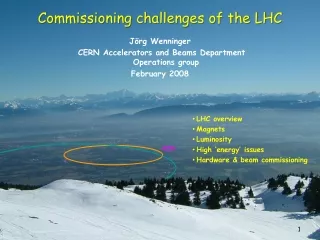
Large Hadron Collider (LHC) • LHC is a two-ring superconducting accelerator and pp collider of 27 km • The dipoles operate at 8.3 T, cooled by superfluid helium at 1.9 K. • Electrical Distribution Feedboxes (DFB) provide the electrical supply to the superconducting magnets • The LHC ring consists of 8 sectors each divided in: regular arc (ARC, ~2.5 km), 2 dispersion suppressors (DS, ~0.5 km), and 2 long straight sections (LSS, ~0.5 km) • The LHC operation and monitoring require a massive amount of cryogenic instrumentation channels • The cryogenic control system has to manage more than 16000 cryogenic sensors and actuators
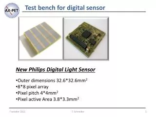
Instrumentation Electronics • More than 800 instrumentation crates are installed, connected and tested underground. They house electronic cards for the temperature (TT), pressure (PT) and liquid helium level (LT) measurements, supply electrical power to the cryogenic heaters (EH) and read the digital valve status • Communicate through a FieldBus, based on the WorldFip protocol. • Four Test Benches have been built at CERN to ensure the correct functionality of all electronics (three of them are used for tests and the fourth for debugging-development and for the pressure sensors calibration).
Instrumentation Electronics Instrumentation readout performed through 2 field-busses Profibus for valve signals. Located at 4 underground protected areas and connected through optic fiber to two PLC (ARC/LSS-surface) WorldFIP for TT, PT, LT and heaters. Up to 80 crates (radiation tolerant) distributed in the tunnel, other 20 crates/sector in protected areas. Two Supervisions Systems in parallel: SCADA-CRYO for the LHC cryogenic operation (synoptic channels for navigation, monitoring and control of all instruments, alarms and interlocks handling, real-time and historical trends, data/event logging and archiving) CIET (Cryogenic Instrumentation Expert Control) for the access to the data of the WorldFIP instrumentation channels (remotely monitor, configure, parameterize and reset read-out channels)
Mobile Test Bench • The MTB is based on a PXI platform, running LabVIEWTM application. The PXI rack houses: • An embedded controller by National Instruments, running Windows XP. • Two FIP communication cards for the top and bottom level of the crates with different FIP addresses. • A 276×8 matrix module by Pickering for the switching of connections between the MTB instrumentation and the cards/cables under test. • One programmable resistor module by Pickering for the simulation of the various sensors during the card tests. • Various other cards (power supply card, multimeter card).
Mobile Test Bench • Other important components of the MTB are: • One Keithley 2400 SourceMeter for resistance measurements in 2-wire mode and current sourcing for the 4-wire measurements. • One Keithley 2182 Nanovoltmeter for accurate voltage sensing for the 4-wire measurements. • A connector panel, which provides the physical interface between the MTB instrumentation and the cards/cables under test. • One heater card test box, which houses power relays that are used to route power from the heater card to the load during the heater card test (PXI matrix can’t handle the current drawn by the load). • One UPS, which supplies all MTB electronics with AC mains power (removal of the MTB from one crate to another, without to shut it down).
Mobile Test Bench • The MTB project uses Perforce (Software Configuration Management tool). Provides a centrally managed storage area for all files and keeps detailed track of the history of each file (versions, changes, bug-fixes, comments, etc). • Perforce manages the software (LabVIEW), configuration files and results. • All crate data stored in layout database. XML data files (CIDs, FIP addresses, type of cards, active channels, cable numbers, type of sensors etc) are used to overcome constraints such as size and complexity of layout database, network presence and speed at the tunnel • The test results are stored locally in the PC and after the completion of tests are submitted to the Perforce server and MTF. • MTF is the quality assurance tool for the LHC equipment. Provides info about the status of a crate commissioned or not (pending, in progress, done).
Mobile Test Bench The following tests are performed with the MTB Consistency test: verification of matching of the crate configuration with the CERN Layout DataBase Card test: check electronic cards functionality Instrument test: check instruments presence and their functionality Pin-to-Pin test: validation check for cables and connectors (short circuits, low insulation resistance) FIP test: functionality verification of the full readout chain (sensor+electronics)
Monitoring Monitoring is a useful tool that shows all the measurements the crate performs (crate not powered, missing or not connected cable, instrument improperly installed, card not operational). It provides an overview of all data that the crate feeds to the FIP network (sensor measurements, noise levels, card state etc).
Consistency test Purpose of the test is the comparison of the crate configuration with the CERN Layout DataBase
Card test Purpose the test is the validation of the correct functionality and accuracy of each electronic card. The criteria pass/fail (reference values, tolerances, etc) are hard-coded in the MTB software, implemented for every card type.
Instrument test Purpose of the test is verification that each instrument (sensor/actuator): is physically present at the machine is correctly wired and properly connected has the expected resistance value, given the instrument type and the machine conditions Method for TT, PT, LT: 4-wire measurement. Uses two pairs of wires, one pair to apply excitation current and another pair to measure the voltage drop across the sensor.
Pin to Pin cable test Purpose of the test is the detection of electrically measurable errors in cable/instrument (short circuits and low insulation resistance) Measurement of the resistance between all pin combinations of a cable connector and the resistance between each pin of the connector and ground in 2-wire mode
FIP test FIP test is the last MTB test FIP functionality is already checked during the card test. FIP test is useful as a final cross check as it requires all the cables to be connected back to the crate. The 4-wire resistance value of the sensor is returned. Comparison with the 4-wire measurement of the instrument test.
Troubleshooting tools Problems: electronic card, instrument, cable, bad contact, short circuit, open circuit, wrong grounding, missing info in the database, FIP communication or a component of the MTB itself. Troubleshooting tools: stand-alone load (connector with discrete resistors internally connected), digital multimeter matrix relay test and cabling test. Purpose of the matrix relay test is to check the MTB matrix for stuck open relays or relays with worn out contact. Measures the resistance of all possible paths (relay combinations) and reports all paths with resistance value higher than a predefined limit. Purpose of the cabling test is to identify possible short circuits in the MTB wiring. Includes the matrix, the connector panel and the MTB cables.
Mobile test bench • The MTB is a valuable tool for finding most problems with cables, sensors and connectors (i.e. wrong or not connected cables to the field instrument, wrong grounding/shielding in the cables or connectors, blown fuses, damaged cables or connectors, missing connections and mismatches with specifications and database).
Mobile test bench • Three mobile test benches in parallel • Two shifts per day (morning/evening) when necessary • The test duration varies between 2 and 10 hours/crate • The rate ~2-3 crates/MTB/shift in average for the ARC (tunnel) and ~1 crate/MTB/shift for the LSS (protected areas) • Duration 2-3 weeks per sector (tunnel) and 1 week for protected areas depending on problems • Second or third pass after the repairs for cross check • Increased experience accelerated the procedure
Conclusions • Relatively complicated tool with long debugging period for exhaustive checks • Increased responsibility of the operator for results interpretation/evaluation and reporting • Useful tool for the electronics troubleshooting • Approximately 800 electronic crates and more than 12000 cryogenic sensors and actuators have been tested in total. • Operational performance (within specifications) has exceeded 98% for thermometers and ~100% for other instruments.
Acknowledgements • We would like to thank our colleagues from the NTUA for their contribution to the project • We have also to deeply thank Dr. Juan Casas-Cubillos and Dr. Paulo Gomes as well as all the members of CERN AT/CRG/IN and AGH, University of Science and Technology for their support, help and contribution • We wish to express our gratitude to Prof. Evangelos Gazis and Prof. Manolis Dris from NTUA and also to Dr. Manolis Tsesmelis and Dr. Roberto Saban, who put in place the Hardware Commissioning Collaboration. • This work was supported by CERN under the collaboration agreements K1208/AT/LHC, K1257/AT/LHC and K1397/AT/LHC.