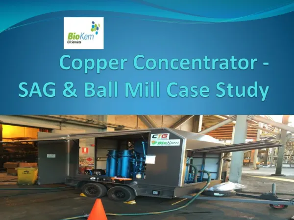
Optimizing Concentrator Control: Sigurd's Rules for CV1 Selection in Evaporation Processes
This document outlines key strategies for controlling a three-stage evaporation process using Sigurd's rules for CV1 selection. It emphasizes the importance of managing active constraints, particularly purity constraints on costly products, and cautions against controlling variables that reach extremes at the optimum. It details cost considerations, feed parameters, and essential system dynamics, including degrees of freedom and optimal operational strategies. Practical examples illustrate effective alternative control configurations and the necessity for self-optimizing variables.

Optimizing Concentrator Control: Sigurd's Rules for CV1 Selection in Evaporation Processes
E N D
Presentation Transcript
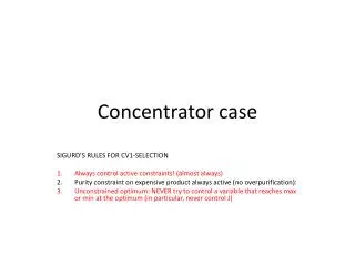
Concentrator case SIGURD’S RULES FOR CV1-SELECTION Always control active constraints! (almost always) Purity constraint on expensive product always active (no overpurification): Unconstrained optimum: NEVER try to control a variable that reaches max or min at the optimum (in particular, never control J)
Three-stage evaporation process V’A Vapor V’ (+ loss of H) Feed F xHF ~ 50% A V’B VA Steam V B LA z V’C VB LB C • MV = [z, zA, zB, zC] (steam valves) • Main disturbances: F, xHF • Product must be on spec (xH = 70%§ 1%; “active constraint”). • (May explode if xH > 75%) • Cost, J = cost steam + loss H= c1 V + c2 V’ yH • Some facts: V’ ¼ V [kg/s] (from energy balance). • Loss H is minimum when V is minimum, so may use cost J=V VC Product, LC xH = 70%§ 1%
Step-wise plantwide control procedure Vapor V’ (+ loss of H) • Cost J=V • (a) Degrees of freedom. 4 dynamic ( z, zA, zB, zC) but only 3 steady-state (VA, VB, VC) since V = VA+VB+VCh (b) Optimal steady-state operation • Product constraint active (xH=70%) • 2 remaining unconstrained DOFs • 2 steam splits: VA/V, VB/V • Optimum: About equal splits (1/3) • Optimum is very flat Feed F xHF ~ 50% A VA Steam V B z VB C VC V+1% Product, LC xH = 70%§ 1% Vopt VB/V VA/V
Step 3. Economic CVs (CV1) V’ • CV1 = [xH,?,?] ¼ [TC,?,?] • Need two “self-optimizing variables” • Some candidates: • xHA, xHB(or TA, TB) • Two of VA/V, VB/V, VC/V • Combinations of these • Other? F A VA Steam V B VB C VC Product xH = 70%§ 1%
Original control system(not working well) Feed F QA = UA(TsA-TA) QB= UA(TsB-TB) QC= UA(TsC-TC) Steam V CV1 = [V/F ,psA, psB,] = [V/F ,TsA,TsB] MV = [z, zA, zB] • No!! Do NOT control J=V !! • TC(xC) not controlled • TsteamA,B are not good self-optimizing variables
Alternative1 Feed F Steam V Same: CV1 = [V/F ,psA, psB,] = [V/F ,TsA,TsB] Different: MV = [zC, zA, zB] • No!! Do NOT control J=V !! • TC(xC) not controlled • TsteamA,B may not be good self-optimizing variables
Alternative 2A Feed F TA Steam V TB CV1 = [V/F , TA, TB] MV1 = [zC, psA, pSB] (cascade) MV = [zC, zA, zB] • No!! Do NOT control J=V !! • TCnot controlled
Alternative 2B (attempted implemented; closing all loops did not work) Feed F Steam V TB TC CV1 = [TC , V/F , TB] MV1 = [pSC, zA, pSB] (cascade) MV = [zC, zA, zB] • No!! Do NOT control J=V !!
Alternative 3 = 2A without ps-cascades Feed F Steam V CV1 = [V/F , TA, TB] MV = [zC, zA, zB] • No!! Do NOT control J=V !! • TCnot controlled
Alternative 4 Feed F TA Steam V TB TC CV1 = [TC , TA, TB] MV1 = [zC, pSA, pSB] (cascade) MV = [zC, zA, zB] • CV1 is OK!! • But: Quite different from original
Alt 5. Implemented Feed F (VC/V)S TA Steam V TB TC (VC/V)S CV1 = [TC , TA, TB] MV1 = [VC/V, pSA, pSB] (cascade) MV = [zC, zA, zB] • CV1 is OK!! • MV1 similar to original CV1 (ratio)
A small summary of our discussions and findings. • V = steam flow (with distribution VA, VB, VC) • F = peroxide feed • LP, VP = peroxide products • Optimal operation can be defined as minimizing the cost J = c1*V + c2*VP*yPwhere V = total steam and VP = vapor loss of peroxide (H2O/H2O2) and yP = faction peroxide in this stream • This cost should be minimized subject to the constraint that we have xC=85% (wt) in the liquid product LC. The pressure p should be within pmin, pmax where pmin=27 mbar and pmax = 35 mbar. The feed (F) is given. • There are four degrees of freedom: VA, VB, VC + p • Note that V (=VA+VB+VC) (steam) and VP (vapor water/peroxide product) are directly related, so both reach minimum at the same point. So, the values of c1 and c2 do not matter! We may as well minimize just one of them. • The optimal solution is approximately to have a distribution 40%, 30%, 30% in the streams FA, FB and FC. But the optimum is very flat, so the exact distribution is not critical. • We have not optimized pressure, partly because we should then also include the cost of the steam for the ejectors. Without the cost of steam for ejectors, I believe that the pressure should be at the minimum, because the relative volatility is usually better at low pressure. In terms of control, it is NOT a good idea to fix the steam to feed ratio (V/F). In general, one should never set directly a variable which is to be minimized (or maximized). The reason is simple: Setting it (V) too low gives infeasible operation (cannot reach xC), and setting it too high means that we are forced to waste steam, which can be achieved by forcing operation to use mainly one of the stages (A, B or C), and there are actually infinitely many ways of doing this. So if we try this control policy, then we will expect problems (as was found in reality when tested).
Sigurd’sforslag (email from Krister 12.06.2013) • PCA 3118 was written to introduce a change in the control structure of the concentrator. • The change was to: • Change E1070A steam flow controller currently a ratio controller to a pressure controller • Change E1070C pressure controller to one controlled by the steam ratio. • Allow E1070A and B stream pressure controller to be controlled by the outlet temperature of the evaporator. • Allow E1070C outlet temperature to control the steam ratio • Install an over ratio trip that isolates the steam to the three chests until reset by the operator
Results • The concentrator was started up and the control loops tuned one at a time. • The start up was no issue and ran smoothly every time we ran it. The % open on the valves for start up was altered after the first run to 5% of PV-1413, 15% on PV-1450 and 10% on FV-1403. This worked well on the next start ups. • The pressure control loops were made faster to respond and this helps with good tight control. This also allows the pressure controllers to be used as part of the start up. • The ratio flow controller is slightly less aggressive than the pressure loops allowing them to settle first. • The temperature control loops are slightly slower allowing steady rate change without large deviation in the ratio. The start-up uses pressure control then when steady the loops are put in cascade. • A 5mBara absolute pressure set point change was handled by the controllers without any major swings • A 500Kg/hr increase and decrease in feed was handled without any major swings. • Although issues were found (see below) overall the system was fit for purpose and the commissioning was complete in one long working day. The control system is now more robust than before the change. The procedures and operational risk assessments have all been updated to reflect what was learnt.
Degasser case CV(alt.2)=liquid fraction MV=V2 CV(alt.1)=vapor fraction