Download
1 / 19
190 likes | 341 Vues
CMS GCT ESR Concentrator Card. 10th May 2006 version 3. Last processing stage before calorimetry data sent to Global Trigger 9U VME64x card 2 DPMCs mounts for electron-leaf cards 2x3 Samtec cables to interface to jet-wheel cards 1 DPMC mount for Global Trigger interface.

E N D
CMS GCT ESRConcentrator Card 10th May 2006 version 3 CMS GCT ESR: Concentrator Card: Greg Iles (gregory.iles@cern.ch)
Last processing stage before calorimetry data sent to Global Trigger 9U VME64x card 2 DPMCs mounts for electron-leaf cards 2x3 Samtec cables to interface to jet-wheel cards 1 DPMC mount for Global Trigger interface What is the concentrator ? CMS GCT ESR: Concentrator Card: Greg Iles (gregory.iles@cern.ch)
Jet interface Arrives from 2 x wheel cards via high speed Samtec cable assemblies 240 LVDS signals from each Wheel card (40 MHz DDR -> 80Mhz) 200 for trigger path 34 for control & readout 2 for clk 4 for jtag Electron interface Arrives from 2 x leaf dual PMC cards mounted on concentrator card Only 206 out of 360 I/O used) 160 for trigger path 40 for control & readout 2 for clk 4 for jtag Incoming data CMS GCT ESR: Concentrator Card: Greg Iles (gregory.iles@cern.ch)
Global Trigger interface Tranmit to Global Trigger on 7 cables 2 unidirectional SerDes channels per cable Each channel driven by NatSemi DS92LV16 Takes 16 bit parallel data at 80MHz. Transmits at 1.44 Gb/s Loopback testing possible with 1 extra cable Mounted on Dual PMC All 360 I/O connected Allows relatively fast & cheap modifications if problems exist with high speed serial links Slink to DAQ Signals connect to VME J2 Uses ECAL transition card to host SLINK transmitter card Outgoing data CMS GCT ESR: Concentrator Card: Greg Iles (gregory.iles@cern.ch)
Processing Two Xilinx Virtex4 FPGAs XC4VLX100-FF1513 Must concentrate large amount of data Choose package with most I/O Integrated differential termination makes layout simpler High speed I/O provide reserve capability Communication Xilinx Virtex2 FPGA XC2V3000-BF957 Robust in 3.3V enviroment VME 64x interface Slink TTCrx Ethernet PHY & USB for future Elec FPGA Isolated Electrons Non-Isolated Electrons Energy Sums Jet Counts Jet FPGA Forward Jets Central Jets Tau Jets Implementation CMS GCT ESR: Concentrator Card: Greg Iles (gregory.iles@cern.ch)
Trigger All paths 40 MHz DDR -> 80MHz Electron η+ data from Leaf DPMC Electron data 2 x 160 Single Ended Via J11, J12, J21, J22 1) Iso Elec 2) Non-Iso Elec 3) Energy Sum 4) Jet Counts Electron η- data from Leaf DPMC Electron V4 FPGA Sorted Et and jet count 2 x 50 Diff Pairs Via Samtec J2 & J3 Global Trigger DPMC 7 x dual channel Serdes links 80 Single Ended Jet η+ data from Wheel Card Leaf Leaf 2 x 180 Single Ended Via fully populated 1/2 DPMC Jet V4 FPGA Leaf Jet η- data from Wheel Card Leaf Sorted & unfinished jets 2 x 150 Diff Pairs Via Samtec J1 & J3 5) Forward Jet 6) Central Jet 7) Tau Jet Leaf Leaf CMS GCT ESR: Concentrator Card: Greg Iles (gregory.iles@cern.ch)
Jet Trigger (a) How to understand the next slide 6 x Leaf (3 per Wheel) 2 x Wheel U2 1 x JetFinder & Cntrl Jet 6 clustered jets (12) & Ht(13) H: ~3x160, R: 3x85 What does this mean ? All numbers in “bits” assuming 80 MHz data transmission on single-ended & differential pairs 6 clustered jets (12) & Ht(13) = 6 clustered jets of 12 bits each and 13bits for Ht per leaf card H: ~3x160 = “Have” aprrox 160 bits from each of the 3 leaf cards R: 3x85 = “Require” 85 bits from each of the 3 leaf cards (6x12+13) Spare capacity on bus Bus at limit, although running at double capacity (160MHz data) should be possible in future CMS GCT ESR: Concentrator Card: Greg Iles (gregory.iles@cern.ch)
Jet Trigger (b) 6 x Leaf (3 per Wheel) 2 x Wheel 1 x Concentrator Comm Et(13), Exy(26) JetCnt(36) H: 2x80, R: 2x75 Ctnrl (64), Et(13), Exy(26GH or 34MH) H: ~3x160, R: 3x111 1) Iso Elec 2) Non-Iso Elec 3) Energy Sum 4) Jet Counts U2 1 x JetFinder & Cntrl Energy Electron SerDes pair (40) H: 180, R: 160 Ht(13) & JetCnt(36) from Eta0 H: 160, R: 49 GT 6 clustered jets (12) & Ht(13) H: ~3x160, R: 3x85 JetCnt(36) H: 160, R: 36 Ht(13) H: 2x20, R: 13 400 SerDes pair (40) H: 180, R: 160 U1 2 x JetFinder Jet Jet 5) Forward Jet 6) Central Jet 7) Tau Jet 8) LoopBack cable 12 clustered jets (12) & Ht(13) H: ~3x320, R: 3x157 12 sorted jets (14) H: 2x174, R: 2x168 Leave at least 2bits per bus for BC0 (equivalent to 1 signal at 80MHz) 3 PreClustered, Unsorted Jets (12GH or 14MH) H: 6x42, R: 6x36 (GH) or 6x42 (MH) CMS GCT ESR: Concentrator Card: Greg Iles (gregory.iles@cern.ch)
Control & Readout 40 MHz DDR -> 80MHz Slink VME TTCrx Clock Control FMM USB Ethernet 1) Iso Elec 2) Non-Iso Elec 3) Energy Sum 4) Jet Counts Electron η+ data from Leaf DPMC 2 x 40 Single Ended Via J23 Electron η- data from Leaf DPMC Electron V4 FPGA Comm V2 FPGA 2 x 32 Single Ended Jet η+ data from Wheel Card Leaf Jet V4 FPGA Leaf 2 x 34 Diff Pairs Via Samtec J2 V2 driving LVDSEXT Leaf 5) Forward Jet 6) Central Jet 7) Tau Jet Jet η- data from Wheel Card Leaf V2 V4 Leaf 100 100 DCI LVDS requires 62.5mW per pair Leaf CMS GCT ESR: Concentrator Card: Greg Iles (gregory.iles@cern.ch)
High speed serial links Susceptible to power supply noise SerDes power will be provided by local linear regulators Mounted on DPMC If design revision necessary cost and turnaround time should be substantially less. PCB layout concerns dominate Must do a reasonable job of length matching Retain option for increased speed Must match as pairs More time consuming that SE bus matching Once again, budget extra time for layout Virtex 4 FPGAs New devices Highly desirable due to enhanced I/O Conservative design requirements Likely requires .0201 decoupling cap scheme Blind/buried vias, small drill diameters .008” used extensively on leaf card Straightforward, but physically large design Layout may be longer than estimated Risk of error or omission higher due to design size Design issues CMS GCT ESR: Concentrator Card: Greg Iles (gregory.iles@cern.ch)
Testing • Connectivity test • Can test connectivity of ~80% of board with either JTAG or custom firmware. • Samtec connections • Loopback with production cables • PMC sites • DPMC test board (Matt Stettler) • FPGA-FPGA connnections • Insitu tests • VME & Slink etc are probably best tested by final or test firmware • E.g. for VME by writing/reading register many times • Alternative is a dedicated JTAG loopback system. • Time consuming to construct CMS GCT ESR: Concentrator Card: Greg Iles (gregory.iles@cern.ch)
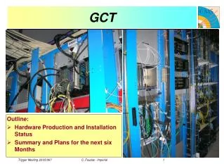
Status of layout CMS GCT ESR: Concentrator Card: Greg Iles (gregory.iles@cern.ch)
Hardware Concentrator currently in layout. Aim to finish before end June Component order to be placed this week or next PCB manufacture & assembly in July Manufacture 6 PCBs Assemble 2 At present 1 month ahead of schedule However need GT DPMC card schematics & layout Firmware VME64x and TTC distribution currently under test in LTC Need to debug serial VME64x Electron Sort by rank in leaf cards & concentrator Jet Eta-0 jets Seed & cluster Convert Et to rank Distinguish between tau, central and forward jets Sort all jet types by ranks GT interface Less than 3 months until boards return Schedule CMS GCT ESR: Concentrator Card: Greg Iles (gregory.iles@cern.ch)
Appendix Following slides list the signal counts and how they were obtained CMS GCT ESR: Concentrator Card: Greg Iles (gregory.iles@cern.ch)
Jet data sent to ‘”Jet’” FPGA Top 4 rank of central, forward and tau jets. Hence 12 objects 12 sorted jets (min 14 bits each) 5 bits phi 3 bits eta (no need for sign) 6 bits rank 9 unsorted jets (min 14 bits each) 18 phi regions -> max 9 jets 1 bit phi (each jet covers 2 phi) 0 bits eta (events in the middle) 10 bits Et 1 bit tau veto 2 bits spare Total = 147 signals @ 80MHz 294 bits Available = 150 signals @ 80MHz Jet data sent to “Elec” FPGA Et-total (13 bits) 12+1 bits mag + overflow Et-missing (26 bits) x & y components 12+1 bits mag + overflow Jet counts (36 bits) 6 jet count regions each 5 bit Alternative more flexible system of 12 jet count regions of 3 bits each (not TDR) Ht (13 bits) 12+1 bits mag + overflow Total = 38 + 7 signals @ 80MHz 75 + 13 bits Available = 40 + 10 signals @ 80MHz Signal: From single Jet-Wheel CMS GCT ESR: Concentrator Card: Greg Iles (gregory.iles@cern.ch)
Electron data sent to ‘”Elec” FPGA Top 4 rank of isolated and non-isolated electrons (min 14 bits each) 8 electron objects (14 bits) 5 bits phi 3 bits eta (no need for sign) 6 bits rank To reduce the latency the FPGAs on the electron leaf card will not share data. Hence each FPGA will send 8 electron objects to the concentrator (i.e. concentrator receives 16 electron objects from each leaf card) Total = 112 signals @ 80MHz 224 bits Available = 160 signals @ 80MHz Signal: From single Elec-Leaf CMS GCT ESR: Concentrator Card: Greg Iles (gregory.iles@cern.ch)
Data transmitted between V4 FPGAs The 9 unsorted jets on the boundary between the two wheels are turned into clusters in the “Jet” FPGA These jets will contribute to Ht and the jet-counts being summed in the “Elec” FPGA Ht (13 bits) 12+1 bits mag + overflow Jet counts (60) 12 types each 5 bits Total = 37 signals @ 80MHz 73 bits Available = 80 signals @ 80MHz Signal: Between Jet/Elec FPGAs CMS GCT ESR: Concentrator Card: Greg Iles (gregory.iles@cern.ch)
Readout Max slink sustained rate = 200 MB/s Assume no source generates more than 100MB/s 10bits @ 80MHz Control Serial VME 2bits L1A & BC0 2bits Serial Fast Commands from TTC B channel (e.g. resync) 1bit AsyncReset 1bit Serial FastFeedback 1bit Total Required = 17 signals Minimum available = 32 signals Signal: Control & Readout CMS GCT ESR: Concentrator Card: Greg Iles (gregory.iles@cern.ch)
Global Trigger interface GT receives 7 cables (2 unidirectional SerDes channels per cable) Each channel driven by NatSemi DS92LV16 Takes 16 bit parallel data at 80MHz. Adds 2 bits. Transmits at 1.44 Gb/s Require 2 bits for powerdown/sync 252 signals (7 x 2 x 18) Require 1 cable for loopback testing Generates 16 bits parallel data Require 4 bits for lock, refclk, powerdown and recovered clk 40 signals (1 x 2 x 20) NatSemi chips do not have JTAG Could use local loopback to test data lines only. Require 2 bits for outenable and local loopback on all chips 44 signals ((14 x 2) + 16 Mounted on dual PMC All 380 I/O connected, Require at least 292 signals, perhaps 336 Slink Signals connect to VME J2 and hence to ECAL transition card Signal: GT interface CMS GCT ESR: Concentrator Card: Greg Iles (gregory.iles@cern.ch)