Download
1 / 22
220 likes | 349 Vues
This document provides an overview of the Source Card ESR design and development status by J. Jones at Imperial College London. It covers various technical aspects including schematic completion, board layout design, and firmware development for the USB and calibration processes. Key features include an auto-calibrated delay for phase matching, data management between channels, and diagnostics support through USB. The current progress is around 90% complete, with expected completion of the layout by late March. Additional details regarding data capture, SERDES connections, and latency estimations are also outlined.

E N D
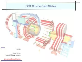
GCT Source Card Design Overview J. Jones (Imperial College London), Source Card ESR
Overview • Source Card Tasks • Separate e/γ from jets • Condense 2x68-way SCSI (RCT) 4x1.6Gbit/s optical fibre • BC0 sync. checking (compare TTC with BC0 embedded in data) • Auto-calibrated delay to phase match data on different channels (if required) • USB 2.0 interface for diagnostic/testing (borrowed from IDAQ-APVE) • Switches data between channels to provide ‘split’ information to leaf cards • Done in FPGA • Extra features • 5 spare LVDS filtered TTC clocks • On-board temperature/status monitoring • Read out either during gaps in data (via concentrator card)…or via USB • Data capture from RCT (for debugging) • Triggered data capture during runtime (for debugging-on-demand) • Internal test pattern generation for testing leaf cards, etc… • Can (in theory) scale to 2x required bandwidth (pin-compatible part) J. Jones (Imperial College London), Source Card ESR
Design Status • Schematic • Currently 90% complete • Few bits left (being done in parallel of layout), being debated (later) • Layout • Should be complete mid-March as expected, end of March at latest • Parts • FPGAs haven’t arrived, but ordered – will chase • Some parts available from other projects (1uF 402 caps etc…) • Need source for free issue components - TTC pin diode, clock buffers • Firmware • USB software & firmware already written, test firmware underway • Major component left is clocking / calibration firmware for data path J. Jones (Imperial College London), Source Card ESR
Board Layout (Schematic) 6 • 10-layer 6U VME form factor • USB 2.0 (Cypress SX2) • TTCrx & QPLL • 2xVHDCI SCSI for RCT input • 4 x Optical SFP output & SERDES • TLK2501 & Agilent HFBR-5720AL • LT1963 low-noise analogue supplies • SERDES driver, QPLL & SFPs • PTH05050 switch-mode supplies • Digital logic, FPGA core & aux • XC3S1000-5FG676C • Please note changes still being made! 4 7 4 2 8 3 5 J. Jones (Imperial College London), Source Card ESR
Board Layout (Artwork) J. Jones (Imperial College London), Source Card ESR
Plane Splitting J. Jones (Imperial College London), Source Card ESR
Clock Distribution Diagram TTCrx QPLL TTC 160/Ext 80 SE Local (40MHz) Clock Splitter (1:10) SERDES EXT FPGA J. Jones (Imperial College London), Source Card ESR
Clock Distribution Details • TTC • Direct from QPLL • Split in dedicated LVDS buffer (MUX of 80MHz & 160MHz) • Running clock through Xilinx FPGA even without DCM can increase phase noise… • 1 clock to FPGA, other 4 to SERDES, 5 spare… • Can also remove jumpers on 160MHz & supply external clock to SERDES & FPGA • Used for testing • Local (40MHz) • Only used for USB and local clock • Always available even if TTC fails or unexpected problem • Safety measure for when things go wrong… J. Jones (Imperial College London), Source Card ESR
SERDES Connections • SERDES Receivers • Due to wiring/DCM constraints, only channel 1a receiver is routed to FPGA • Each link will be tested in turn by connecting 1a receiver to each transmitter • Other SERDES receivers may be routed to a header for future use • SERDES Transmitters • Routing for MGT transmitter links given priority over receiver • Can be discussed in artwork • Transmitter links straight from FPGA, series terminated, 50 Ohm traces • Relative trace lengths of lines to each SERDES matched to TX_CLK length • SERDES clock can be changed between 80MHz, 120MHz, 160MHz & external • Will be fixed in final system J. Jones (Imperial College London), Source Card ESR
Source Card Latency RCT->Leaf (Unregistered) • Madison Cable (quoted from datasheet) • 1.5ns/ft • Assume 5ft max. length => 1.5x5 = 7.5ns delay • ECL Buffers • 2.5ns-6ns (4ns typical) • FPGA (XC3S1000) • 8ns (synthesised) • SerDes • 38 bit-times@1.6GHz (625ps) = 23.75ns • PCB Tracking • Assume 5-inch@300ps/inch = 1.5ns • Optical Fibre (20m) • 100ns • Estimated Total: • 7.5+4+8+23.75+1.5 = ~1.79BX (board & RCT cable) + 4BX (fibre) J. Jones (Imperial College London), Source Card ESR
Source Card Latency RCT->Leaf (Registered) • Madison Cable (quoted from datasheet) • 1.5ns/ft • Assume 5ft max. length => 1.5x5 = 7.5ns delay • ECL Buffers • 2.5ns-6ns (4ns typical) • FPGA (XC3S1000) • (12.5-4-7.5+3+5+3)=12ns (estimated) • SerDes • 38 bit-times@1.6GHz (625ps) = 23.75ns • PCB Tracking • Assume 5-inch@300ps/inch = 1.5ns • Optical Fibre (20m) • 100ns • Estimated Total: • 7.5+4+12+23.75+1.5 = ~1.95BX (board & RCT cable) + 4BX (fibre) J. Jones (Imperial College London), Source Card ESR
Source Card Latency RCT->Leaf (Split-Registered) • Madison Cable (quoted from datasheet) • 1.5ns/ft • Assume 5ft max. length => 1.5x5 = 7.5ns delay • ECL Buffers • 2.5ns-6ns (4ns typical) • FPGA (XC3S1000) • 15ns (guess!) • SerDes • 38 bit-times@2.4GHz (417ps) = 15.85ns • PCB Tracking • Assume 5-inch@300ps/inch = 1.5ns • Optical Fibre (20m) • 100ns • Estimated Total: • 7.5+4+15+15.85+1.5 = ~1.75BX (board & RCT cable) + 4BX (fibre) J. Jones (Imperial College London), Source Card ESR
Source Card Skew (Maximum Limit) • Madison Cable (quoted from datasheet) • 0.025ns/ft maximum • Assume 5ft max. length => 0.025x5 = 0.175ns skew • ECL Buffers • 1ns max. (part-part) • FPGA • Could be O(ns) if unregistered – can be tweaked but not 1st priority. • Negligible skew when registered • SerDes • N/A • PCB Tracking • Can (will) be controlled • Estimated Total: • 0.175+1 = 1.75ns << 12.5ns clock J. Jones (Imperial College London), Source Card ESR
Cabling Requirements • RCT uses SCSI-2 connectors with non-standardpinout • 1-2, 3-4, 5-6… • Big, bulky cable, couldn’t fit on a 6U card • As design is custom, can change connector on our side • New cable is 5ft, 28/30 AWG cable • Getting quote from Tyco • SCSI-2 on RCT end • VHDCI SCSI on source card J. Jones (Imperial College London), Source Card ESR
Board Testing Plan I • Power-Up Testing of Power Supplies • Modular design of power system makes this simple • Power Plane Short Testing • Manual / automatic process, takes ~5 mins • JTAG Testing • Script can be developed at Imperial (done for previous boards) • Script can be sent to assembly company for automated checking • Functionality Testing • Full testing can only be achieved by loading the FPGA • Aim to generate a test firmware • Loop back TX/RX on optical links, one at a time J. Jones (Imperial College London), Source Card ESR
Board Testing Plan II • Need to Test ECL buffers • Could be done using a test card • – need to know what is needed and any ideas for how? • Otherwise need to connect to RCT to test J. Jones (Imperial College London), Source Card ESR
Board Testing Plan III • Firmware Tests • Developed in modules, each of which are part of final system • ECL capture firmware • For testing ECL buffers and proving RCT links work • Test pattern firmware • Developed for BER testing of memory on IDAQ • A-5, random, ramp should be sufficient? • Will be left in for final firmware • PRBS test of optical links • Links will be driven at 120MHz to push limits and check for marginal connections • Eye diagrams will be checked also… • …but need optical probe, don’t have one at IC (CERN?) • First test to be done, internal test built into SERDES • Perform both internally in SERDES & via loopback • Also run other tests both internally & through links • Will show connectivity/PCB and link problems J. Jones (Imperial College London), Source Card ESR
Functionality Testing (Detail) • Software • C++ based via USB 2.0 link • Tested successfully in current project (IDAQ) @ 28MB/s in two days continuous operation (Beam Test) • We now have a working linux driver as well (speed not tested, but not critical) • Firmware • USB firmware complete • Functionality-testing firmware will be developed in parallel with layout and finished after submission of design to manufacture • Drive optical links with psuedo-random, A-5, ramp, pseudo-RCT • Qualify link BER to <10-12 at ~2Gbit/s before use with leaf cards • This will take ~1 hour set-up & test per card • 60 cards = 60 hours week job (apart from failures!) J. Jones (Imperial College London), Source Card ESR
Additional (New) Functionality – To Be Discussed • Histogramming RCT data at run-time • Debugging GCT during ‘real’ runs • Blanking links • Blanking regions • What CRC/FEC? • SERDES pins are all used in jet mode… • This needs to be discussed NOW • Any others? • Would like to pin this down in a REQUIREMENTS DOCUMENT J. Jones (Imperial College London), Source Card ESR
Queries I – SERDES Coupling / Bias Scheme • TLK2501 requires external CML bias • But HFBR-5720AL SFP contains internal caps, so no need to AC-couple outside? • Would like to discuss tracking here… (see artwork after meeting) J. Jones (Imperial College London), Source Card ESR
Queries II – ECL Interface • Originally followed near termination scheme with just ~125 Ohm across pair • Similar to IM on old GCT • Still consider this a bit weird, although discussed with two engineers so far • Was recommended to AC-couple and bias to LVDS levels, but surely then needs to be DC-balanced? • Would like to discuss… J. Jones (Imperial College London), Source Card ESR
Other Issues • Quotations • To be sought next week once final BoM is fixed • Quotations will be sought from Exception, CemGraft, A.N. Other? • Ordering • Order 2 in first batch (submit end March to give time to recheck design) • Order 10 in second batch (submit after tests in April/May?) • Order 48 in third batch (submit after testing with leaf card?) • Testing Schedule • If all goes well, can we test with RCT first? • Leaf card won’t be back to end of June, but source card should be fully tested well before then • I’ll be working in b904 anyway, so would be appropriate J. Jones (Imperial College London), Source Card ESR