Status Update on GCT Source Card Development at Imperial College London
This document details the current status and design summary of the GCT Source Card, developed by John Jones at Imperial College London. The card is intended to capture data from RCT and transmit it via optical links with minimal latency. It features a USB 2.0 interface, multiple SCSI inputs, and will undergo extensive testing plans to ensure functionality. The latest updates include component orders, PCB readiness, and firmware development status, with anticipated completion times provided.

Status Update on GCT Source Card Development at Imperial College London
E N D
Presentation Transcript
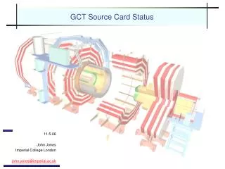
GCT Source Card Status 11.5.06 John Jones Imperial College London john.jones@imperial.ac.uk
Role of the Source Card • Capture data from RCT • Relay data from RCT via optical links to GCT Leaf Card with minimal latency • Provide test pattern transmission to Leaf Card for run-time debugging RCT Crate RCT Crate Leaf Card RCT Crate Source Card Crate Leaf Card RCT Crate RCT Crate John Jones (IC - john.jones@imperial.ac.uk), GCT ESR
Design Summary • 6U VME Card • USB 2.0 Interface • 2xVHDCI SCSI RCT Inputs • 4xSFP optical outputs • TTC input • QPLL, TTCrx • Spartan-3 1M FPGA • Digital/Analogue supplies • Limited spare I/O for debug • Front panel JTAG • Limited remote update ability • On-board LVDS test clock • 6 spare clock outputs John Jones (IC - john.jones@imperial.ac.uk), GCT ESR
Source Card RCT Emulator Card • Developed to drive RCT inputs of source card John Jones (IC - john.jones@imperial.ac.uk), GCT ESR
Source Card Status • Components ordered (awaiting lead time estimate) • PCBs soon ready for manufacture (ahead of components) • Board should be available in 4-6 weeks (depends on component lead time) • Firmware test-benched & synthesised (see later) • Software under development (see J. Brooke’s talk) John Jones (IC - john.jones@imperial.ac.uk), GCT ESR
Source Card Latency I Registered • Initial mode of operation • Easier, but higher latency – can be tuned and not as bad as one might think… • 6+2+(14+)+2+(21.25<->23.75) = 45.25<->47.75ns Source Card 3m, ~15ns BUFFER DECL->TTL RCT VHDCI 6ns Extra register with phase-shifted clock 2ns FPGA 14+ns 21.25-23.75ns 2ns SERDES Leaf ~100ns John Jones (IC - john.jones@imperial.ac.uk), GCT ESR
Source Card Latency II Unregistered • Tricky, not initial mode of operation as skew in FPGA difficult to control • Phase of SERDES clock controlled via CLKDES on TTCrx • 6+2+10+2+(21.25<->23.75) = 41.25<->43.75ns • Doubtful whether this will be worth the effort… Source Card 3m, ~15ns BUFFER DECL->TTL RCT VHDCI 6ns 2ns FPGA 10ns 21.25-23.75ns 2ns SERDES Leaf ~100ns John Jones (IC - john.jones@imperial.ac.uk), GCT ESR
Source Card Firmware - Architecture RCT Data LED Encoder TTC Interface TTC I2C Temp. I2C Data Capture System Interface Wishbone Transcoder USB EMU/JET Switch Wishbone Bridge Transmitter Control Bit Mask RAM Counter LFSR Transmitter FSM CRC-16 TTC Clock A-5 SERDES Clock Data MUX Local Clock SERDES John Jones (IC - john.jones@imperial.ac.uk), GCT ESR
Source Card Firmware - Status RCT Data LED Encoder TTC Interface TTC I2C Temp. I2C Data Capture System Interface Wishbone Transcoder USB EMU/JET Switch Wishbone Bridge Transmitter Control Bit Mask RAM Counter LFSR Transmitter FSM CRC-16 A-5 Real-World Tested Data MUX Simulated SERDES John Jones (IC - john.jones@imperial.ac.uk), GCT ESR
Source Card Testing Plan I • Drive RCT inputs using Source Card Test Card via IDAQ • Send via IDAQ USB, readout via Source Card USB • Synchronising clock provided locally / via TTC • Verify A-5, PRBS, counter TTC Source Card SCTC RCT IN IDAQ FPGA USB USB OPTO 1 CLKBUF OPTO 2 OPTO 3 OPTO 4 John Jones (IC - john.jones@imperial.ac.uk), GCT ESR
Source Card Testing Plan II • Demonstrate fake data capture at leaf • Synchronise via TTC / local TTC Source Card SCTC RCT IN IDAQ FPGA USB OPTO 1 CLKBUF OPTO 2 LEAF OPTO 3 OPTO 4 John Jones (IC - john.jones@imperial.ac.uk), GCT ESR
Source Card Testing Plan III • Demonstrate RCT data capture in Source Card • Synchronise via TTC TTC Source Card RCT RCT IN FPGA USB USB John Jones (IC - john.jones@imperial.ac.uk), GCT ESR
Source Card Testing Plan IV • Demonstrate RCT data capture at Leaf Card • Synchronise via TTC / local TTC Source Card RCT RCT IN FPGA USB OPTO 1 CLKBUF OPTO 2 LEAF OPTO 3 OPTO 4 John Jones (IC - john.jones@imperial.ac.uk), GCT ESR
Proposed Source Card Crate Layout • 4 Source Card crates serve 18 RCT crates John Jones (IC - john.jones@imperial.ac.uk), GCT ESR
USB 2.0 Hardware Interface Source Card Source Card Source Card Source Card Source Card Source Card Source Card Source Card Source Card Source Card Source Card Source Card Source Card Source Card Source Card Source Card Source Card Source Card VMEbus SBC running Linux 7-port USB hub 7-port USB hub 7-port USB hub 7-port USB hub 3 front panel USB port Internal Hard drive To monitor a 12-card crate Pentium Processor 10/100Base TX Ethernet To monitor a 15-card crate John Jones (IC - john.jones@imperial.ac.uk), GCT ESR
USB 2.0 Hub Board Artwork for hub mounting card has been completed and prototype is in production at Imperial John Jones (IC - john.jones@imperial.ac.uk), GCT ESR
Summary • Submission of Source Card PCB slightly delayed… • …but other associated components on track… • Plan to complete interfaces (software/PC) before PCB return in mid-late June John Jones (IC - john.jones@imperial.ac.uk), GCT ESR