Download
1 / 14
140 likes | 340 Vues
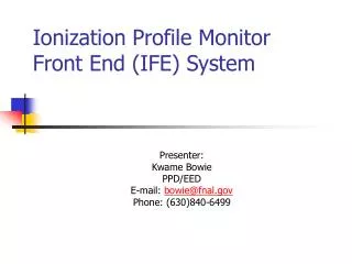
Ionization Profile Monitor Front End (IFE) System. Presenter: Kwame Bowie PPD/EED E-mail: bowie@fnal.gov Phone: (630)840-6499. IPM System Diagram. Upstairs. IPM Timing Card. In Tunnel. 1 CAT5 cable. Timing System. DAQ PC. Horiz. MCP. IPM FE Crate. 128 channels. IPM Buffer

E N D
Ionization Profile MonitorFront End (IFE) System Presenter: Kwame Bowie PPD/EED E-mail: bowie@fnal.gov Phone: (630)840-6499
IPM System Diagram Upstairs IPM Timing Card In Tunnel 1 CAT5 cable Timing System DAQ PC Horiz. MCP IPM FE Crate 128 channels IPM Buffer Cards 16 optical fibers Readout System Front End System Detector System Timing System IPM Timing Card 1 CAT5 cable DAQ PC Vert. MCP IPM FE Crate 128 channels Readout System IPM Buffer Cards 16 optical fibers Detector System Front End System
Front End System Requirements • Capable of per-bunch resolution in both time and integrated charge • Capable of instrumenting 256 microchannel plate (MCP) channels simultaneously • Propagates ALL data upstream for sparsification/triggering in the IPM Buffer Cards • All components in tunnel are rad-tolerant
IPM Front End System Components • Two (2) separate IPM planes (horizontal and vertical) may be treated as separate subsystems • Each IPM plane is instrumented by a single IPM Front End crate • Each IPM crate contains: • One (1) custom IPM Backplane for power distribution • One (1) IPM Fanout card for clock distribution • Sixteen (16) IPM Front End (IFE) boards digitizing MCP charge
Pbar revolution marker Fanout card Proton revolution marker 15.2 MHz 2RF/7 Encoded Control Clock (15.2MHz) Proton Mrkr PBar Mrkr Control Backplane QIE (8 QIEs) 16 IFE Board power connectors Anode stirp signals (~128) 16 serial links (optical fiber) ~1.6 Gbits/s/link ~23 Gbit/s total QIE IPM Front End System Diagram
IPM Front End BackplaneDesign • Custom Backplane required due to high power consumption of rad-tolerant ECL components • Custom backplane has four (4) high-current connectors which provide power to the Front End Boards as separate quadrants. • Power is provided by a custom 3-phase rectifier circuit (J. Zagel) that also is rad-tolerant.
IPM Backplane Block Diagram Backplane Quadrant A: 5 Slots Slot0: Fanout Slots1-4: IFEs Quadrant B: 4 Slots Slots5-8: IFEs Quadrant C: 4 Slots Slots9-12: IFEs Quadrant D: 4 Slots Slots13-16: IFEs 6V @10A 6V @8.5A 6V @8.5A 6V @8.5A 8V @4A 8V @4A 8V @4A 8V @4A
IPM Fanout Card Design • IPM Fanout card receives a 2RF/7 clock and beam-synchronous timing flags from the IPM Timing Card (T. Fitzpatrick) • IPM Fanout card is charged with providing low skew copies of this clock to all 16 IFEs in the crate to ensure simultaneous digitization on all cards
IPM Front End (IFE)Functionality Each IFE board digitizes 8 channels of MCP signal using 8 QIEs for the integration • Each IFE board multiplexes these 8 channels of QIE data along with beam-synchronous timing information into a single fiber with a data payload of roughly 1.2Gbps • Only two operational modes for the IFE boards: normal mode and calibration mode • Boards ALWAYS send ALL data upstream to IPM Buffer card
QIE 9bits@2RF/7 9bits@2RF/7 QIE MCP Analog Inputs QIE 9bits@2RF/7 Rad-tolerant Antifuse FPGA GOL 32bits@40Mhz QIE 9bits@2RF/7 9bits@2RF/7 QIE QIE 9bits@2RF/7 Optical Transmitter QIE 9bits@2RF/7 9bits@2RF/7 QIE IFE Board Data Flow Diagram 1.6Gbps CML 1.6Gbps optical
IPM Front End System Design Tradeoffs and Decisions • Cost vs. radiation tolerance • Power consumption vs. radiation tolerance • Board/crate size vs. channels per board
IPM Front End (IFE) Board Specifications • The IFE board integrated charge resolution is < 1fC • The IFE board sampling (integration) period is ~15MHz • Board size: 6U x 160mm • Components Cost: $350/ board excluding QIEs, GOL, regulators • Power Consumption: 12Watts/board
Calibration • Decided against on-board charge injection mechanism for three (3) reasons: • Possible noise concerns • Possible charge sharing issues • Board space concerns • Advantages of off-board calibration: • Calibration uses entire system and full data path, so it may be used as a system level functionality test • Can be compared to results from LeCroy ADCs to verify accuracy • Disadvantages of off-board calibration: • Calibration requires lots of hardware • Calibration very slow
Calibration Setup (Lab6 setup) Pulse enable (NIM) NIM to TTL IPM Timing Card Laser Control PC Trigger (TTL) Encoded Injection Trigger (PECL) analog current pulse QIE output IPM Front End Board PMT Pulse laser (NIM) analog current pulse Delay and Gate Generators Dye and Filter Wheels Light LeCroy ADC ADC output Laser Photo Diode Light