Download
1 / 12
120 likes | 268 Vues
Summary of visit to BNL and LARP workshop High Bandwidth Feedback perspective. Preliminary Report by W. Hofle 21.05.2014. Overview. Monday: discussions on stochastic cooling with colleagues from BNL, LLRF and transverse feedback;

E N D
Summary of visit to BNL and LARP workshop High Bandwidth Feedback perspective Preliminary Report by W. Hofle 21.05.2014
Overview • Monday: discussions on stochastic cooling with colleagues • from BNL, LLRF and transverse feedback; • Tuesday: dedicated Highbandwidth Feedback meeting jointly with • M. Brennan and M. Blaskiewicz, LARP team present • (J. Fox, O. Turgut, C. Rivetta, S. de Santis) + remote participants • (presentations LHC feedback, SPS feedback, • stochastic cooling in RHIC) • https://indico.fnal.gov/conferenceDisplay.py?confId=8477 • Wednesday • Thursday: official LARP part, dedicated session on feedback, • kickers, power amplifiers , reduced models, electronic hardware, • and summary presentation by J. Fox in plenary session https://indico.bnl.gov/conferenceDisplay.py?confId=730
Phased Schedule decisions phase 3: LHC post LS1 Physics Run LS1 Year 1 LS2 Year 2 Year 3 2019 2011 2012 2013 2018 2014 2015 2016 2017 Phase 1: Demonstrator 1 New Kicker New Power amplifiers Phase 2: Bunch Train Demonstrator R&D and operation New Pick-up R&D / prototyping ? as proposed July 2013 Electronics R&D phase 2 beam tests with Bunch trains (ecloud) Scrubbing beam In ramp and at 450 GeV flat top Phase 3: Full implementation
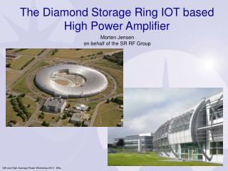
Location of Kickers, Infrastructure • SPS Sextant 3, LSS3 • Housed in the second half of the 321 period of the SPS. • Approximately 8 m of usable space following the dipole magnet • 8 new 7/8” cables pulled to kicker location during LS1 • Power amplifiers still needed • Essential for operation of new kickers! • Critical items for post LS1 operation Courtesy of E. Montesinos LARP/HiLumi Collaboration Meeting, CM22
Full Assembly - CAD • The stripline kicker essentially transforms the amplifier output voltage applied at the downstream feedthroughs into a transverse force applied to the travelling particles (integrated deflecting voltage) 40 mm 156 mm 92 mm 55 mm S. De Santis – May 7th , 2014 15
Beam Induced Voltage • The stripline characteristic impedance has been designed to be 50 Ω in the kicking mode (odd TEM), but it is 74 Ω for the even TEM mode. • Usual remedies (ground planes) are not practicable due to large horizontal stay-clear requirements. • Beam induced voltage on downstream port (i.e. the amplifier’s) have been estimated by analytical models (time domain, frequency domain) and simulations (Particle Studio) S. De Santis – May 7th , 2014 17
Power Amplifiers Evaluation Time-domain measurements • Evaluation of 4 power amplifiers in 2013, loaned to us by manufacturers (work by K. Pollock) • Amplifier Research 250W1000AM4 • Amplifier Research KAW-2300 (modified) • MilMega 80RF1000-250 • R&K GA020M102-5454R • Developed testing methods and procedure to characterize amplifiers in both time and frequency domains • Typical frequency domain measurements with network and spectrum analyzers, measure frequency response, phase linearity • Time-domain measurements performed with 4 GS/s high speed DAC with the capability of generating arbitrary signals • Burst signals, much like those needed for feedback • R&K (Japan) seemed to have most desirable characteristics in time-domain, but tests on going • Specifications: • Frequency = 20 – 1000 MHz • Power = 250 – 500 W • Instantaneous BW • 100% amplitude modulation • Linear phase across band Time (ns) Time (ns) Time (ns) Time (ns) LARP/HiLumi Collaboration Meeting, CM22
R&K (Japan) • We are working with manufacturers to improve impulse response and fidelity of amplifiers • Cater to our specifications • Expect modified amplifier to test from R&K • R&K time-domain test using a 40 MHz burst signal • Able to remove tail of signal • Many manufacturers don’t have the capability to make the time-domain measurements we do • Therefore, we need to use our equipment to fully characterize the amplifiers • Status on R&K • As of April, they’ve informed us that they need to redesign the 90 degree hybrid combiners • Seems to be a common issue using several stage amplifiers • Additional 2.5 months of development Before After R&K’s impulse response measurements LARP/HiLumi Collaboration Meeting, CM22
New Power Amplifier Developments • We’ve reached out to additional amplifier vendors and have had a very positive response of interest in working with us • Additional companies • Rhode & Schwarz • AR Pennsylvania • Intertronic Solutions • Rhode & Schwarz • Most amps are developed for broadcasting transmission purposes • Berlin development laboratory, a 80 – 1000 MHz, 125 W module, with goal of 1 kW in summer 2015. • Sent us preliminary result, using 200, 400, 800 MHz continuous input signals at 100 W output • Another case where the vendor does not have the equipment necessary to properly characterize the amplifier for our needs. They have invited us to Berlin to test the amplifier with our high speed DAC • Very excited to work with us, “…we will do everything humanly possible to make sure we are your amp of choice.” Rhode & Schwarz test of BC125 400 MHz Source Signal Amp Output LARP/HiLumi Collaboration Meeting, CM22
Plans for immediate future • Power system • Strip-line kickers to be installed before start-up with beam • Set of power amplifiers / alternative: use existing power amplifiers, two amplifier companies seem to qualify, R&K (Japan), R&S Berlin, ramp-up CERN involvement in the selection and purchase • Re-work phase compensation and signal splitting (new cables, different transfer function) • Expanded demonstrator • FPGA code for bunch trains (planned was 48 bunches) 16 bunches now considered feasible • No dedicated FPGA code for bunchlet scrubbing (24x2 bunches) • Control algorithmn for Q20 • Pick-up • keep existing PU system for the moment, possibility to use old or new cables • Clocks: • Revisit synchronization with SPS clocks, tests w/o beam end of August