Download
1 / 11
110 likes | 469 Vues
Image Co-alignment of Solar-B SOT/XRT/EIS Data. T. Shimizu (ISAS/JAXA). Introduction. Solar-B. Position information is included in Solar-B image header In order to indicate where on the disk is observed. Mainly used for database search and operation planning

E N D
Image Co-alignment of Solar-B SOT/XRT/EIS Data T. Shimizu (ISAS/JAXA) Extended SOT17@NAOJ
Introduction Solar-B • Position information is included in Solar-B image header • In order to indicate where on the disk is observed. • Mainly used for database search and operation planning • Accuracy may not be adequate for data analysis. A few tens arcsec deviation at worst case. • Image co-alignment needs to be performed in data analysis • To co-align among data from Solar-B telescopes • Relative relation among the telescope pointings • 0.5 arcsec or better accuracy required • To co-align Solar-B data with data from other observations • Other observations: satellites, ground-based • Absolute coordinate on the solar disk • ~1 arcsec accuracy required Extended SOT17@NAOJ
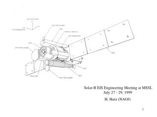
Telescopes are mounted on “stable” cylindrical optical bench (OBU) • However, each telescope pointing has different orbital variation due to thermal deformation including barbecue effect OBU 2D trajectory map of orbital variation of pointings) (Prediction based on thermal deformation test, Hot case) Extended SOT17@NAOJ
Baseline between-telescopes alignment procedure Common solar features are used to co-align the data from different telescopes with each other. Common features are sunspots seen both in SOT continuum/G-band image and XRT VLS images. Accuracy is in order of 0.1 arcsec. Images of interest Need a visible image in XRT sequence within ~10 minutes There is a time gap between sunspot image and images of interest. The time series of each telescope’s images are co-aligned by the procedure shown later. Extended SOT17@NAOJ
Between-telescopes alignment procedure (1)Co-Alignment between XRT and SOT Solar-B Zoom up time Images of interest for comparison Extended SOT17@NAOJ
Between-telescopes alignment procedure (2)Co-aligning series of SOT images Solar-B SOT (Filtergram, Spectro-Polarimeter) Data time • Satellite jitter is already removed in series of SOT images • Tip-tilt mirror with correlation tracker removes satellite jitter • Tip-tilt mirror control tracks the group motion of granules seen in the correlation-tracker’s field of view (11x11arcsec). • If 0.5km/s group flow exists in CT FOV, • 600 sec (10 min) period produces ~0.4 arcsec alignment shift. Extended SOT17@NAOJ
Between-telescopes alignment procedure (3)Co-aligning series of XRT images Solar-B XRT and EIS Data time S/C jitter • Satellite jitter is included in series of XRT images. • Sun sensor (UFSS)’s information can be used to remove satellite jitter. Sensor’s random error is ~0.3 arcsec (0-p). Extended SOT17@NAOJ
Between-telescopes alignment procedureXRT VLS micro-vibration concern Solar-B • There is a concern on slight degradation of SOT image performance when XRT VLS (visible light shutter) is rotating (< a few sec). • VLS produces fairly large micro-vibration during its rotation, which may shake SOT optics during the rotation. • (Result from satellite-level micro-vibration test) • 10 minutes cadence of VLS images may not be performed. If not, VLS cadence may be once per orbit (90 min). • Alternate co-alignment concept may apply (next page). Extended SOT17@NAOJ
Alternate co-alignment concept (by SAO) SOT No limb info in data (x0,y0) (x1,y1) (x’p,y’p) Sunspot ‘position’ wrt the limb is interpolated from (x0,y0) and (x1,y1) Includes drift due to granule motions Short-term satellite jitter removed with UFSS data XRT X-ray Visible light Visible light X-ray (x0,y0) (x1,y1) Sunspot ‘position’ wrt the limb (xp,yp) at the corner of FOV is known from the X-ray limb and UFSS Alignment using limb for ~45min (max) ~90min t0+90min t0 t Extended SOT17@NAOJ
Co-Alignment with Non-Solar-B Data Solar-B • To co-align Solar-B data with data from other observations • Other observations: satellites, ground-based • Absolute coordinate on the solar disk • ~1 arcsec accuracy required • The way to have ~1 arcsec • accuracy in absolute coordinate • is to use limb position in full- • disk images from XRT. Extended SOT17@NAOJ