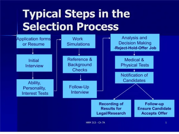
Typical Steps of field Balancing
600 likes | 1.05k Vues
Balancing Training Part 1. Typical Steps of field Balancing. Illustration with model 907. E-mail: sales@sendig.com , sendigbj@yahoo.com.cn Telephone: +8610 82895321 Fax: +8610 82895320 http://www.sendig.com. An Overview of the Steps. Collecting Machine data Preparing Instrument & Sensor

Typical Steps of field Balancing
E N D
Presentation Transcript
Balancing TrainingPart 1 Typical Steps of field Balancing Illustration with model 907 E-mail: sales@sendig.com, sendigbj@yahoo.com.cn Telephone: +8610 82895321Fax: +8610 82895320 http://www.sendig.com
An Overview of the Steps • Collecting Machine data • Preparing Instrument & Sensor • Balancing really required ? • Balancing possible ? • Procedure of balancing
Step 1 - Collecting Machine data • Understand the machine to be balanced as much as possible • Collect machine data • Take a photo of the machine
Sample: Machine to be balanced • Impeller Parameter: • Diameter: 1400mm • Thickness: 500mm • Blade Number: 12 • Material:Fiberglass-Reinforced • Plastics • RPM: 1825 r/min • Bearing Model: ? • MotorParameter: • Power: 75kW • RPM: 1500 r/min • Others: • Belt transmission • Spring base • Manufacture: LG Bearing1 Bearing2 Impeller Motor
Step 2 - Preparing Instrument & Sensors • Sendig-904/907 dual-channel data collector/analyser/balancer • A notebook computer • Sendig-MCM3 Analysis Software
Sensors & Cable connecting Attach reflecting paper on shaft
Step 3 - Balancing really required? • Use 904/907 to measure overall vibration values • Compare with ISO Standard 2) Use “Collector” to measure vibration 1) Switch to Analyzer
Horizontal VELOCITY is the critical parameter 6: Point: Motor-1-Side-2-X Alarm-mode: Displacement Freq-Range: 500Hz Sensor:4.6 ………………………… New Data Old Data ACC xxx / xxx m/s2 VEL 7.2 / 2.1 mm/s DISP 68 / 12 µm ENV xx / xx m/s2
Sample Overall Value Measurement Acc. Vel. Disp. Envelope Peak ms-2 RMS mm/s P_P um RMS ms-2 Hor. 88.81 9.95 101.5 5.268 Ver. 55.89 5.554 38.77 7.362
Sample Not Permissible, Balancing really required ! Measurement 9.95 mm/s
Step 4-1: Balancing possible?–“single peak spectrum”? • Use 904/907 to measure vibration spectrum • Only “single peak spectrum” can go for balancing 2) Use “Collector” to measure vibration 1) Switch to Analyzer 3) Use “C-Spect” to see velocity spectrum
Sample of non-single peak spectrum- not suitable for Balancing
Sample of non-single peak spectrum- Better change bearing before balancing
Sample of single peak spectrum – You can reduce the vibration by Balancing
Step 4-2: Balancing possible ?–“90o phase difference”? • Use 904/907 to measure vibration phase difference between vertical and horizontal directions • Only “90o phase difference” can go for balancing 3) See if “90o phase difference” exist? 1) switch to balancer and use 2-planes balancing procedure 2) Page down to “Initial Measurement” to measure vibration phase at X & Y
Sample Sample of “non-90o phase difference” – You cannot reduce the vibration by Balancing • Phase Measurement: • Velocity Amplitude Phase • Vertical: 9.416 320 • Horizontal: 3.08 116 Phase difference not 90o Since phase difference is not 90o nor closer to 90o ,this means the problem with the fan is something else other than unbalance.
Sample Sample of nearly “90o phase difference” – You can reduce the vibration by Balancing • 1. Phase stable • 2. Phase Measurement: • Velocity Amplitude Phase • Vertical: 0.693 73 • Horizontal: 1.569 150 Phase difference is 77o ?
Balancing TrainingPart 2 Procedure of balancing
Different Kinds Of Imbalance 2-plane imbalance 1-plane imbalance
Characteristics Of Imbalance 1. The vibration frequency is mainly composed of RPM frequency. For each round the rotor turns, a vibration is occurred. 2. The wave is an approximate sine wave. 3. There is a difference of 90o between the vertical vibration phase and the horizontal one. 4. With RPM increasing, the vibration amplitude is increased
A phase RPM amplitude Basic Principle Of 1 Plane Balancing 1 select a plane to fix trial mass and a point to measure, draw scale of phase and sign of 0o phase 2 measure initial vibration A0(phase and amplitude) 3 fix a trial mass Q on the plane, measure vibration A1 4 calculate influence coefficients: 5 calculate balancing mass P:
A1- A0 o A1 A0 K Q o P Illustration of 1 Plane Balancing • draw A0 &A1, calculate A1-A0 • measure the angle between A1-A0 and A0 • turn Q aalong the direction of , gain the correct location of balancing mass. • the weight of balancing mass is as the following :
Method of Influence Coefficients • Method of influence coefficients is widely used, its step as the following (1 plane balancing as example): 1 measure initial vibration 2 fix a trial mass 3 measure the vibration with the trial mass 4 calculate the result of balancing mass
IF THE INFLUENCE COEFFICIENTS ARE KNOWN, THE STEP OF FIXING TRIAL MASS ARE IGNORED The former steps are simplified as the following: 1) measure initial measurement 2) input influence coefficients 3) calculate the result of balancing mass
phase Reflecting slice NOTICES DURING THE OPERATION • Confirm the dynamic balancing are needed according to spectrum and phase analysis. • Direction of phase: reverse to the direction of rotation
SELECTING PARAMETERS • Measure displacement or velocity for middle or low speed machines • Measure velocity or acceleration for high speed machines
CONFIRM whether the trial is suitable • The radius of loading trial mass is as same as loading the amended mass • The turning speed is steady
Tacho sensor A Accelerometer 907 1-PLANE BALANCING Without influence coefficients
Operation Basic • Prompt is displayed at the last line • Press ‘∧’ and ‘∨’ key to move the cursor up and down • Press Enter to select iterm • Press number keys to input digits • To other MENU, press PgDn or PgUp
Always make sure the “Setting” is correct before the balancing Enter a digit, select 1 set of data from 10 Enter a digit, select plan number Change by “ENTER”, use displacement or velocity for most machines Input sensitivity (from accelerometer certificate)
INITIAL MEASUREMENT • Press Enter to measure rotation speed first • Press Enter for a moment to measure vibration after rotation speed become steady • After phase and amplitude become steady, press Enter for a moment to end the measurement
TRIAL ESTIMATION • Input the 4 parameters • When cursor on 6th line, press Enter to calculate trial range • Stop the machine, fix a trial mass according to the range
TRIAL MEASUREMENT • Input phase and weight of the trial, confirm whether it will be removed afterward, restart the machine • Move cursor to 6th line, press Enter to measure rotation speed • When RPM steady, press Enter a moment to measure vibration • When amplitude and phase steady, press Enter for a moment to end the measurement
TRIAL RESULT • See what the 6th line shows • If YES displayed, press Pg Dn to go on • If NO displayed, stop the machine, adjust trial mass, return to the early page of TRAIL MEASUREMENT, measure again
Cursor on 2nd line, press ENTER to calculate influence coefficients The result is shown in 4th line Cursor on 2nd line, press Enter to calculate balancing mass The result is shown in 3rd line CALCULATION
Input the 2 angles Display the results If nothing displayed at right side, change the order of the 2 angles and re-enter Pa2 Pa Pa1 Decomposing/Splitting
VERIFICATION • Cursor on 2nd line, press Enter to measure rotation speed • When RPM steady, press Enter a moment to measure vibration • When amplitude and phase steady, press Enter for a moment to end the measurement • The last 2 lines displays the results
1-PLANE BALANCING With influence coefficients, you do not need to add trial mass. You need only measure the initial vibration
SETTING PARAMETERS Set “Yes” for the question of “Have influence Coefficient?”
INITIAL MEASUREMENT • Press Enter to measure rotation speed • Press Enter for a moment to measure vibration after rotation speed become steady • When phase and amplitude become steady, press Enter for a moment to end the measurement
Move the cursor to the 4th line, input amplitude and angle of coefficient Press Pg Dn to the next page INPUT COEFFICIENTS
Pa2 Pa Pa1 Calculation, Decomposition & verification • calculate balancing mass • Decomposition and verification are the same as illustrated earlier
2-PLANES BALANCING Without influence coefficients The main difference than 1-plane: • Need to add trial mass one after another at the 1st plane and 2nd plane • Need to use 2 vibration sensors
Sensors & Cable connecting Attach reflecting paper on shaft
INITIAL MEASUREMENT & TRIAL ESTIMATION Get 2 lines of reading here
TRIAL I MEASUREMENT • Input phase and weight of the trial on plane 1, decide if it will be removed, restart the machine
TRIAL II MEASUREMENT • Input phase and weight of the trial on plane 2, decide if it will be removed, restart the machine
Pa2 Pb2 Pa Pb Pb1 Pa1 Calculation, Decomposition & Verification • calculate balancing mass • Decomposition and verification are the same as illustrated earlier