Lab02 :Logic Gate Fundamentals:
Lab02 :Logic Gate Fundamentals:. The NOT gate:. Slide #2. The OR gate:. Slide #3. The AND gate:. Slide #4. OFF. OFF. OFF. ON. ON. ON. 5v. Input A. Output X. Logic 1. Logic 1. Logic 1. Logic 0. Logic 0. Logic 0. Lab 02:The NOT Gate (inverter):.

Lab02 :Logic Gate Fundamentals:
E N D
Presentation Transcript
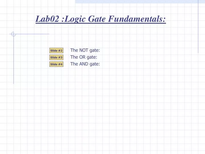
Lab02 :Logic Gate Fundamentals: The NOT gate: Slide #2 The OR gate: Slide #3 The AND gate: Slide #4
OFF OFF OFF ON ON ON 5v Input A Output X Logic 1 Logic 1 Logic 1 Logic 0 Logic 0 Logic 0 Lab 02:The NOT Gate (inverter): The NOT gate is the first of the three fundamental logic gates. You will learn its operation using Truth Table analysis and an animation. Truth Table: Is a chart that lists the input condition on the left and the gate’s output response on the right. The table shows that the NOT gate responds at the output with the inverse of the signal applied to the input. Animation: In order to see how it works, the gate has been connected to a switch and LED. Continue to see the system in action… Slide #2
Logic 1 Logic 1 Logic 0 Logic 1 Logic 1 OR 5v Input A Output X Input B Logic 1 Logic 0 5v Logic 0 Logic 1 Logic 1 5v Logic 0 Logic 0 Lab 02: The OR Gate: The OR gate is the second of three fundamental logic gates. You will learn its behaviour using a Truth Table analysis and an animation. Truth Table: The table shows that the OR gate responds with a high at the output if the signal applied to the input A or B is high. Animation: In order to see how it works, the gate has been connected to 2 switches and LED. Continue to see the system in action… Slide #3
Logic 1 Logic 1 Logic 1 5v Logic 1 Logic 0 AND Logic 0 Logic 0 5v Input A Output X Logic 0 Logic 0 Input B 5v Logic 0 Logic 1 Logic 0 Lab 02: The AND Gate: The AND is the last of the remaining fundamental logic gates. You will learn its behaviour using a Truth Table analysis and an animation. Truth Table: The table shows that the AND gate responds with a high at the output if the signal applied to the input A and B are both high. Animation: In order to see how it works, the gate has been connected to 2 switches and LED. Continue to see the system in action… Slide #4