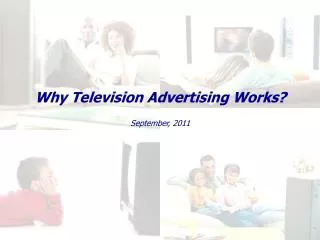
How Television Works?
How Television Works?. “A Simplified Viewpoint??”. From Studio to Viewer. Television content is developed in a studio from a variety of sources Live televised events Pre-recorded events Combination of both. How the image makes it into your living room…. The Camera Imaging sensor

How Television Works?
E N D
Presentation Transcript
How Television Works? “A Simplified Viewpoint??”
From Studio to Viewer • Television content is developed in a studio from a variety of sources • Live televised events • Pre-recorded events • Combination of both
How the image makes it into your living room… • The Camera • Imaging sensor • Imaging Tube (old) • CCD or CMOS (new) • http://electronics.howstuffworks.com/camcorder2.htm • More about cameras later this semester.
Transmission of Audio and Video Signals • The image captured is combined with other electronic content (text and graphics) plus audio. • The combined image is amplified and transmitted via AM (amplitude modulation) and FM (frequency modulation) carrier waves to either a satellite feed or from direct transmission to a television receiver.
The receiver decodes the signal • The electronic signal is decoded by the receiver; splitting the FM wave to the audio section and the AM wave to the video section of the television. • http://www.howstuffworks.com/tv.htm
The Black-and-White TV Signal • In a black-and-white TV, the screen is coated with white phosphor and the electron beam "paints" an image onto the screen by moving the electron beam across the phosphor a line at a time. • To "paint" the entire screen, electronic circuits inside the TV use the magnetic coils to move the electron beam in a "raster scan" pattern across and down the screen. The beam paints one line across the screen from left to right. It then quickly flies back to the left side, moves down slightly and paints another horizontal line, and so on down the screen, like this:
The Black-and-White TV Signal In a black-and-white TV, the screen is coated with white phosphor and the electron beam "paints" an image onto the screen by moving the electron beam across the phosphor a line at a time. To "paint" the entire screen, electronic circuits inside the TV use the magnetic coils to move the electron beam in a "raster scan" pattern across and down the screen. The beam paints one line across the screen from left to right. It then quickly flies back to the left side, moves down slightly and paints another horizontal line, and so on down the screen, like this: The Black-and-White TV Signal • The blue lines represent lines that the electron beam is "painting" on the screen from left to right, while the red dashed lines represent the beam flying back to the left. When the beam reaches the right side of the bottom line, it has to move back to the upper left corner of the screen, as represented by the green line in the figure. When the beam is "painting," it is on, and when it is flying back, it is off so that it does not leave a trail on the screen. • As the beam paints each line from left to right, the intensity of the beam is changed to create different shades of black, gray and white across the screen. Because the lines are spaced very closely together, your brain integrates them into a single image. A TV screen normally has about 480 lines visible from top to bottom.
Early Television Imagery • Early Television did had lower scan rates and reduced image quality. • As image capture devices improved after the National Television System Committee (NTSC) established standards by which broadcasters and manufacturers alike adhered. • Interlaced transmissions became an early standard.
Interlaced Images • Interlaced images allow for easier transmission of moving images at higher resolution. • Half pictures in 1/60th a second..30fps. • Trade offs include some image jitter: • Jagged edges from motion occur because the object is in a different location every 1/60 of a second. The even lines show the object in one position while the odd lines show the image in a different position.
Interlaced Images • Motion artifacts and horizontal "line twitter" are the most notorious NTSC artifacts. • The closer you sit to your video display device and the larger the video display device appears, the easier it will be to see NTSC artifacts in images. • Some newer television sets employ powerful image processing that can make NTSC artifacts very difficult to find. HDTV (high-definition digital television) includes standards for higher-resolution progressive scanning, which eliminates the video image artifacts we have endured for over 50 years. • Unfortunately, many HDTV products have chosen the higher resolution 1080i format (1080 lines interlaced) to use to convert everything regardless of how it was broadcast or recorded. This is unfortunate because interlace artifacts remain quite visible even in the 1080i format.
Color TV Screen • A color TV screen differs from a black-and-white screen in three ways: • Three electron beams (Red, Green, Blue)that move simultaneously across the screen. • The screen is coated with red, green and blue phosphors arranged in dots or stripes. • On the inside of the tube, very close to the phosphor coating, there is a thin metal screen called a shadow mask. This mask is perforated with very small holes that are aligned with the phosphor dots (or stripes) on the screen. • .
Color TV Screen • To create a white dot, red, green and blue beams are fired simultaneously -- the three colors mix together to create white. The absence of signal is black. • All other colors on a TV screen are combinations of red, green and blue
Composite Video Signal • A signal that contains all three of these components -- intensity information, horizontal-retrace signals, and vertical-retrace signals -- is called a composite video signal. • One line of a typical composite video signal looks something like this: • The horizontal-retrace signals are 5-microsecond (abbreviated as "us" in the figure) pulses at zero volts. Electronics inside the TV can detect these pulses and use them to trigger the beam's horizontal retrace. The actual signal for the line is a varying wave between 0.5 volts and 2.0 volts, with 0.5 volts representing black and 2 volts representing white. This signal drives the intensity circuit for the electron beam. In a black-and-white TV, this signal can consume about 3.5 megahertz (MHz) of bandwidth, while in a color set the limit is about 3.0 MHz. • A vertical-retrace pulse is similar to a horizontal-retrace pulse but is 400 to 500 microseconds long. The vertical-retrace pulse is serrated with horizontal-retrace pulses in order to keep the horizontal-retrace circuit in the TV synchronized.
Color Phase Burst 0 degrees Yellow 15 degrees Red 75 degrees Magenta 135 degrees Blue 195 degrees Cyan 255 degrees Green 315 degrees A black-and-white TV filters out and ignores the chrominance signal. A color TV picks it out of the signal and decodes it, along with the normal intensity signal, to determine how to modulate the three color beams. • Following these eight cycles, a phase shift in the chrominance signal indicates the color to display. The amplitude of the signal determines the saturation. The following table shows you the relationship between color and phase:
Color TV Signal A color TV signal starts off looking just like a black-and-white signal. An extra chrominance signal is added by superimposing a 3.579545 MHz sine wave onto the standard black-and-white signal. Right after the horizontal sync pulse, eight cycles of a 3.579545 MHz sine wave are added as a color burst.
Next Week: How Television Programming is developed…