Download
1 / 54
550 likes | 643 Vues
Explanation of magnetic fields, forces, and electromagnetic waves. Learn about magnetic dipoles, torque on current loops, and force on moving charges. Discover the relationship between electric charges and magnetic fields.

E N D
Magnetic Fields and ElectromagneticWaves • If the bar magnet is suspended by a thread or supported by a pivot, one of the ends will point in a northerly direction. This end of the magnet is called the north pole of the magnet, with symbol N. The opposite end of the magnetic is called the south pole, with symbol S. • Elementary experiments show that like poles repel and unlike poles attract. • There is something that we call a magneticfield by which poles can exert forces on each other.
If we break a bar magnet in half, we can not make single poles, but instead we will have two bar magnets. • There is an intimate relation between the motion of electric charges and magnetic field.
Magnet Fields • The magnet fields are indicated by continuous lines from the north to the south pole, and the number of lines is arbitrary (see Fig. 16-1) . • The direction of the magnet field for a long, straight wire is schematically represented in Fig. 16-2. The field becomes weaker as we move away from the wire. • See Fig. 16-3. The arrows represent the magnetic field direction inside the loop. These field lines return outside the loop so that the loop itself becomes a magnet.
Force on Current-Carrying Wire • Experiment shows that when a wire carrying a current is placed in a magnetic field, it will experience a force. • Fig. 16-4 is a schematic drawing of an experiment which shows that when a wire carrying a current is placed in a magnetic field B the force F is in a direction that is perpendicular to the plane defined by the field and the direction of the current. • The force F is proportional to the sine of the angle θ between the field and the wire.
The SI unit for B is newtons/ampere-meter (N/A-m) and named Tesla (T). An old unit for the magnetic field is the Gauss (G), where 1 tesla = 104 gauss. • The earth's magnetic field is about 10-4 T. • The direction of the force induced by magnetic field and a current-carrying wire is the perpendicular both to the magnetic field and to the direction of the current. Thus, • It is conventional to let the current i be a scalar quantity and to let be a vector pointing in the direction of the current.
Torque on a Current Loop • Consider a single rectangular loop of wire connected to a pivot rod, as shown in Fig. 16-5. For sides 1 and 3 the magnitudes of the forces are the same because the angle between and B is and both wires have the same length a, that is, • From the definition of the cross product, F1 is out of the page toward the reader whereas F3 is into the page.
Similarly, the magnitudes of the forces on sides 2 and 4 are equal, that is, • The direction of F2 is upward, while that of F4 is downward. • See Fig.16-5b. If we look at the top view along the pivot rod we see that there exists a torque that tends to rotate the loop about the pivot rod.
The result is the same for any other geometric configuration. • The torque is a maximum when θ = , that is, when the plane of the loop lies in the direction of B. • The torque is zero when θ= , that is, when B is perpendicular to the plane of the loop. • The magnitude of the angle of rotation is a function of the current passing through the coil. • A way of increasing the torque on the coil is by using a coil made of several loops.
Magnetic Dipole Moment • The magnetic dipole moment or simply the magnetic moment μ of the coil is defined as • The expression for the torque can now be written as • We define the direction of μ is the perpendicular to the plane of the loop according to the right-hand rule. Thus,
Because a magnetic dipole experiences a torque when placed in an external magnetic field, work must be done by an external agent to change its orientation. This work becomes the potential energy Ep of the dipole. • It is customary to set Ep = 0 when , that is, the dipole vector is perpendicular to the magnetic field.
Since the cosθ varies between 1 and -1, the maximum energy and minimum energy are μB and -μB, respectively.
Example 16-1 • Assume that the electron in a hydrogen atom is essentially in a circular orbit of radius , and rotates about the nucleus at the rate of 1014 times per second. What is the magnetic moment of the hydrogen atom due to the orbital motion of the electron?
Sol where i is the current due to a single electron. Because current is defined as the amount of charge passing per unit time, we have where v is the frequency of rotation and e is the magnitude of the charge of the electron.
Force on a Moving Charge • We know that where q is the magnitude of a charge, N the number of charge carries per unit volume, A the cross-sectional area, and v the average drift velocity of the charge carriers.
The force per charge carrier Fq is • We assume that v is in the same direction as and therefore the current. • Because F is perpendicular to v the magnetic field does no work on the charge. The magnetic field does not change the magnitude of the velocity of the charged particle.
The Hall Effect • Consider the system shown in Fig. 16-6. Let the direction of the magnetic field be into the paper, indicated by the symbol , which suggests the tail of an arrow. • See Fig. 16-7. • This force causes the positive charges to move to the upper part of the conducting strip while they are moving to the right. • Because the sample as a whole must remain neutral, the lower part of the strip will become negatively charged.
The accumulation of positive charges along the upper part and of negative charges along the lower part creates an electric field that opposes the further upward drift of positive charges. • There will be a potential difference VHbetween D and C associated with this electric field. where it is assumed that in equilibrium is constant and d is the width of the strip.
This voltage difference is called the Hall voltage and the phenomenon is called the Hall effect. • The equilibrium Hall voltage VH will be established when the downward force equal the upward force resulting from the magnetic field. • At equilibrium
Because the Hall voltage can be readily measured by connecting a voltmeter between D and C, the Hall effect permits the experimental determination of the drift velocity of the charge carriers. • An alternative form of VH: where RH = 1/qN is called the Hall coefficient.
Because I, B, and t are measurable, the magnitude of the Hall voltage will yield the value of N, the density of charge carriers. • Let us consider the negative charge carriers in the Hall effect (see Fig. 16-8). Although the velocity vector v is reversed, the direction of the force given is still upward because the charge q is negative. • The upper part of the strip will have an accumulation of negative charges and the lower part an accumulation of positive charges. • The polarity of the Hall voltage will tell which type of carriers is responsible for conduction.
Example 16-2 • A current of 50 A is established in a slab of copper 0.5 cm thick and 2 cm wide. The slab is placed in a magnetic field B of 1.5 T. The magnetic field is perpendicular to the plane of the slab and to the current. The free electron concentration in copper is 8.4 ×1028 electrons/m3. What will be the magnitude of the Hall voltage across the width of the slab? • Sol :
Electromagnetic Waves: The Nature of Light • Starting with the fundamental laws of electromagnetism, J. Maxwell showed that accelerated charges would produce electromagnetic waves whose velocity of propagation c through free space should be • An electromagnetic wave consists of an electric field and a magnetic field B perpendicular to each other with both and B perpendicular to the direction of their propagation.
If we measure the value of E and B at difference points along the x axis, at some fixed times t we will observe that both E and B vary sinusoidally with x. • If we sit at a fixed point in space and measure E and B at that point as a function of time, we observe that both vary sinusoidally with time. • Any charge distribution that oscillates sinusoidally with time should produce electric and magnetic fields that behave as described by the above equations.
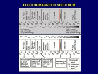
The frequency of the electromagnetic wave should be the same as the frequency of oscillation of the charges producing it. • No motion of material particles is involved in the electromagnetic wave, hence, there is no need for a medium of propagation. • All electromagnetic waves should travel with velocity • See Table on page 245 of the textbook. • The laws of electromagnetic waves apply to waves of the entire electromagnetic spectrum.
Homework • 16.3. 16.4, 16.5, 16.6, 16.8, 16.10, 16.11, 16.14, 16.15, 16.17, 16.18, 16.19, 16.20.
The Doppler Effect • If you are driving toward the police car that is parked by the side of the highway and sounding its siren, you will hear a higher frequency. If you are driving away from the police car you will hear a lower frequency. • These motion-related frequency changes are examples of the Doppler effect. • The Doppler effect holds not only for sound waves but also for electromagnetic waves, including microwaves, radio waves, and visible light. • Police use the Doppler effect with microwaves to determine the speed of a car : a radar unit beams microwaves of a certain frequency v toward the oncoming car.
We will measure the speeds of sources S of sound waves and a detector D of those waves relative to that body of air. • We shall assume that S and D move either directly toward or directly away from each other, at speeds less than the speed of sound.
Detector Moving; Source stationary • See Fig. 16-s1. A detector D is moving at speed vDtoward a stationary source S that emits spherical wavefronts, of wavelength λ and frequencyν, moving at the speed v of sound in air. • Let us for the moment consider the situation in which D is stationary (Fig. 16-s2). The number of wavelengths in the distance vt is the number of wavelengths intercepted by D in time t, and that number is =¸. The rate at which D intercepts wavelengths, which is the frequency ν detected by D, is
16-s2 16-s1
See Fig. 16-s3. Let us again consider the situation in which D moves opposite the wavefronts. In time t, the distance moved by the wavefronts relative to D is vt + vDt. The number of wavelengths in this relative distance vt + vDt is the number of wavelengths intercepted by D in time t, and is (vt + vDt)/λ. Then rate at which D intercepts wavelengths in this situation is the frequency , given by
The frequency detected by D if D moves away from the source is
Source Moving; Detector Stationary • Let detector D be stationary with respect to the body of air, and let source S move toward D at speed vS (Fig. 16-s4). • The motion of S changes the wavelength of the sound waves it emits, and the frequency detected by D.
Let T (= 1/ν) be the time between the emission of any pair of successive wavefronts W1 and W2. During T, wavefront W1 moves a distance vT and the source moves a distance vST. At the end of T, wavefront W2 is emitted. In the direction in which S moves, the distance between W1 and W2, which is the wavelength of the waves moving in that direction, is vT -vST. If D detects those waves, it detects frequency given by
In the direction opposite that taken by S, the wavelength of the waves is vT + vST. If D detects those waves, it detects frequency given by • When both the source and the detector can be moving with respect to the air mass we have which is the general Doppler effect.
The Doppler Effect at Low Speeds • The Doppler effects for a moving detector and for a moving source are different, even through the detector and the source may be moving at the same speed. • If the speeds are low enough (that is, if and ), the frequency changes produced by these two motions are essentially the same. • Let and we want to approximate the value (a + b)n. We have where x = b/a. By binomial theorem,
and when x is small. • By using the binomial theorem, we have in which is the relative speed of the source with respect to the detector. If the source and the detector are moving toward each other, we anticipate a greater frequency; this requires that we choose the plus sign. On the other hand, if the source and the detector are moving away from each other, we anticipate a frequency decrease and choose the minus sign.
Example 16-s1 • A toy rocket at a speed of 242 m/sec directly toward a stationary pole (through stationary air) while emitting sound waves at frequency = 1250 Hz. (a) What frequency is sensed by a detector that is attached to the pole? (b) Some of the sound reaching the pole reflects back to the rocket, which has an onboard detector. What frequency does it detect? (Assume that the sound speed is 343 m/sec.)