Spin Oscillator Experiment Setup with Solenoid Coil and Optical Components
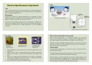
This setup outlines the experimental framework for a spin oscillator experiment utilizing a solenoid coil to create a static magnetic field of B0 = 30.6 mG at a current of I = 7.354 mA. The apparatus includes a 4-layer magnetic shield made of permalloy, a Si photodiode, and a bandwidth ranging from 0 to 500 kHz. A quarter plate heater facilitates spin precession signals from a pumping laser at 794.76 nm (Rb D1 line), with a power of ~11 W. The system also incorporates a 129Xe gas cell under specific pressure conditions for optimal experimental results.

Spin Oscillator Experiment Setup with Solenoid Coil and Optical Components
E N D
Presentation Transcript
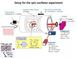
Setup for the spin oscillator experiment Solenoid coil (static field) ・B0 = 30.6 mG (I = 7.354 mA) magnetic shield (4-layer) ・permalloy Si photodiode ・Bandwidth: 0 ~ 500 kHz l/4 plate Heater spin precession signal Pumping laser ・l = 794.76 nm (Rb D1line) ・Dl = 3 nm ・Power ~ 11 W PEM 129Xe gas cell 129Xe : 230 torr N2 : 100 torr Rb : ~ 1 mg Pyrex glass SurfaSil coating Probe laser ・DFB laser ・l = 794.76 nm (Rb D1line) ・Dl = 8.4×10⁻⁶ nm ・Power : 15 mW 18 mm