Uranium Neutrino Experiment Setup
140 likes | 237 Vues
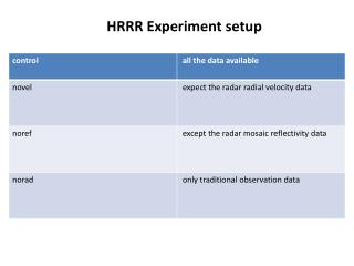
Detailed setup and beam optics for the neutrino line experiment using Uranium species. Methods for reducing beam particles at the target and stripping effects discussed.

Uranium Neutrino Experiment Setup
E N D
Presentation Transcript
Schematic diagram of Booster_BtA_AGS Complex SS_A06 Injection Point and Matching point SS_A05_kicker SS_L20_Injection Septum L20 Pos. & Ang. Inj. Bumps AGS G and H extraction bumps to AtR BtA H10 Extraction Septum to AtR SS-H13 Start AtR Line Booster Exit SS_F6_Septum Extraction Point Beginning of BtA U_Line Extraction Bumps SS_F03_kicker
Schematic arrangement of current transformers and Flags/stripping foils in the U/W line during U+90 +91+92transport 4.250 bend U+90 +91 +92 U+90 80 bend uxf1 200 bend Uf1 Uf2 W foil 0.025 mm Uf3 Uf4 Uf5 uxf3 Au+77 +78 +79 Wf1 wxf1 U+90 +91 +92 Uf1,Uf2,Uf3,Uf4, Uf5 (2 mil Gd2O2S:Tb on 1 mil Al subtray) Wf2 Wf1,Wf2, Wf3 (2 mil Gd2O2S:Tb on 1 mil Al sub tray) Wf3
Uranium beam at AGS Extraction • species 238U+90 • B=92.816 Tm • rel=0.995125 • =10.14065 • t=25 ns
Beam Optics (AGS to target of Neutrino Line) • Establish circulating beam in AGS at extraction energy with extraction bumps turned on. • Start at G10 kicker location (G10 kicker ON) and transport the beam down to neutrino line. • Constrains used in beam transport: • Maintain beam size to clear beam apertures. • Beam achromatic at the target location???
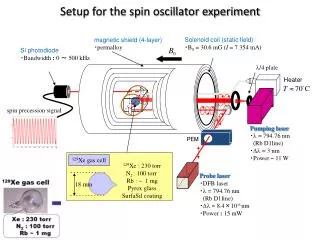
How do we reduce the beam at the target to 5000 particles/bunch • Focus the U+90 on target and use dipole and quadrupoles to deflect the core of the beam and also defocus it. • Focus the U+90 on target and use insert the Wsripperand/or the Uf2 flag to strip away the tripped U ions and hope the intensity of the unstripped ions is good enough to be detected at the target. Alternatively change the setting of the 8o bend to allow the U+91beam which has higher intensity.. • Focus the U+90 on target and use insert flags down stream of the 8obend. Defocus the beam using Q10 to Q13 qudrupoles.
Stripping of 10.3 GeV/n Au+77 ions Using: a) 1.0 [mm] Al2O3 b) 0.025 [mm] W foilc) 0.051 [mm] Gd2O2S:Tb on 0.0254 [mm] Al Only results from measurements are presented. For any other information on the measurements please conduct tsoupas@bnl.gov tsoupas@bnl.gov
Schematic arrangement of incoming Au+77 ions, the stripping foil and the ions emerging after the foil Au+77 Au+77 Au +78 Au+79 Stripping foil tsoupas@bnl.gov
Measurements of some quantities after stripping.See next slide for explanation * The symbol “<“ in the Table signifies that the value of the measured quantity is below the resolution of the measuring device.
Explaining the Table of the previous slide tsoupas@bnl.gov