Electrical Actuation System
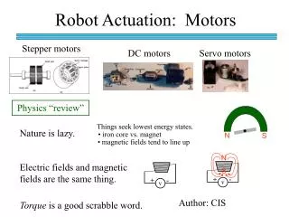
Electrical Actuation System. Lecture 9 (Chapter 9). Introduction. The electrical systems used as actuators are: Switching devices – mechanical switches and solid-state switch Solenoid type device Drive system – motors (AC, DC, Stepper). 7.5: DC Motor.

Electrical Actuation System
E N D
Presentation Transcript
Electrical Actuation System Lecture 9 (Chapter 9)
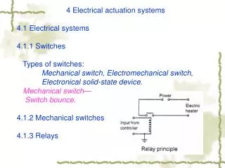
Introduction • The electrical systems used as actuators are: • Switching devices – mechanical switches and solid-state switch • Solenoid type device • Drive system – motors (AC, DC, Stepper) SME 3252: Mechatronics Lecture 7
7.5: DC Motor • Has six basic parts -- axle, rotor (a.k.a., armature), stator, commutator, field magnet(s), and brushes • The stator is the stationary part of the motor -- this includes the motor casing, as well as two or more permanent magnet pole pieces • The rotor (together with the axle and attached commutator) rotates with respect to the stator. The rotor consists of windings (generally on a core), the windings being electrically connected to the commutator SME 3252: Mechatronics Lecture 7
SME 3252: Mechatronics Lecture 7 http://hyperphysics.phy-astr.gsu.edu/hbase/magnetic/motdc.html
7.5.1: DC Motor Operation SME 3252: Mechatronics Lecture 7 http://hyperphysics.phy-astr.gsu.edu/hbase/magnetic/motdc.html
a) Current in DC Motor SME 3252: Mechatronics Lecture 7 http://hyperphysics.phy-astr.gsu.edu/hbase/magnetic/motdc.html
b) Magnetic Field in DC Motor SME 3252: Mechatronics Lecture 7 http://hyperphysics.phy-astr.gsu.edu/hbase/magnetic/motdc.html
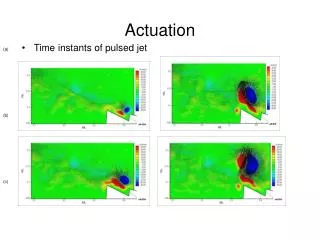
c) Force in DC Motor SME 3252: Mechatronics Lecture 7 http://hyperphysics.phy-astr.gsu.edu/hbase/magnetic/motdc.html
d) Torque in DC Motor SME 3252: Mechatronics Lecture 7 http://hyperphysics.phy-astr.gsu.edu/hbase/magnetic/motdc.html
Voltage • DC motors are non-polarized - can reverse voltage without any bad things happening • Typical DC motors are rated from about 6V-12V • Motors operate at different voltages because voltage is directly related to motor torque • More voltage, higher the torque • A DC motor is rated at the voltage it is most efficient at running • Apply too few volts, it just won’t work. If apply too much, it will overheat and the coils will melt • General rule - try to apply as close to the rated voltage of the motor • Recommendation - do not surpass 12V SME 3252: Mechatronics Lecture 7
Torque • two torque value ratings given: operating torque - the torque the motor was designed to give and stall torque - the torque required to stop the motor from rotating • Torque ratings can change depending on the voltage applied SME 3252: Mechatronics Lecture 7
3 ways to brake DC motors • Controls MethodRequires an encoder placed onto a rotating part of DC motor. Write an algorithm that determines the current velocity of motor, and sends a reverse command to H-bridge until the final velocity equals zero • Mechanical MethodThe mechanical method is what is used on cars. Something with very high friction and wear resistance is needed, e.g. a servo actuated brake l. • Electronic MethodThe least reliable, but the easiest to implement. The basic concept of this is that if the power is shorted and ground leads motor, the inductance created by motor in one direction will power motor in the opposite direction. Although motor will still rotate, it will greatly resist the rotation. SME 3252: Mechatronics Lecture 7
Connect a MOSFET (transistor) and a relay as shown • The MOSFET turns on the relay, which creates a short between the motor leads • Turn the MOSFET on (set C high) with microcontroller to brake the motor • Basically the motor will still have an H-bridge for normal control • When braking, the H-bridge is turn off and use the braking circuit SME 3252: Mechatronics Lecture 7
7.5.4: Control of d.c. motor • Control d.c. motor speed from microprocessor – pulse width modulation or PWM • Taking a constant dc supply voltage and chopping it so that average voltage is varied • PWM can be obtained using basic transistor circuit • Transistor is switch on and off based on signal applied to its base (for one direction movement) • H circuit (four transistors) – enable motor to be in forward and reverse direction SME 3252: Mechatronics Lecture 7
Closed-loop control • Closed-loop control – use feedback to control motor speed if conditions change • Feedback signal by tachogenerator - which gives analog signal • Feedback signal by encoder – digital signal • System is digital with PWM is used to control average voltage applied to armature SME 3252: Mechatronics Lecture 7
FINAL PROTOTYPE PIC Microcontroller Motor Driver Analog Distance Sensor DC Geared Motor IR Sensor SME 3252: Mechatronics Lecture 7
Advantage and disadvantage of d.c. motor SME 3252: Mechatronics Lecture 7
7.6: AC Motor • AC motors can be classified into 2 – single phase and three phase AC motors • To have 3 phase power on a robot, use either big and expensive DC to AC converter, or tether it to a wall socket • AC motors is used if the robot is stationary, such as a robot arm SME 3252: Mechatronics Lecture 7
Voltage • Polarized (current cannot be reversed) • Typically from 120-240V AC, usually to match mains power • Higher voltages generally mean more torque, but also require more power • Rarely used on mobile robots due to power requirements SME 3252: Mechatronics Lecture 7
Current • 2 types of current: stall and operating current (max and minimum) • Stall Current - The current a motor requires when powered but held so that it does not rotate • Operating Current - The current draw when a motor experiences zero resistance torque • It is best to determine current curves relating voltage, current, and required torque for optimization • When a motor experiences a change in torque (such as motor reversal) expect short lived current spikes • Current spikes can be up to 2x the stall current, and can fry control circuitry if unprotected • Use diodes to prevent reverse current to your circuitry • Check power ratings of your circuitry and use heat sinks if needed SME 3252: Mechatronics Lecture 7
Torque • When buying a motor, consider stall and operating torque (max and minimum) • Stall Torque - The torque a motor requires when powered but held so that it does not rotate • Operating Torque - The torque a motor can apply when experiencing zero resistance torque SME 3252: Mechatronics Lecture 7
Control method • Modifying the AC frequency can alter speed and torque • Encoder - device which counts rotations of wheel or motorshaft to determine velocity for a control feedback loop • Tachometer - device which measures current draw of motor to control output torque • To maintain constant torque at diff speed when freq. varied, a.c. in converted to d.c. by a converter and converted back to a.c. by inverter SME 3252: Mechatronics Lecture 7
Flexible Coupling Magnetic Brake Inductive Proximity Sensor Timing Plate Extension Shaft inverter is to vary the input voltage (stator voltage) into the induction motor PSM student’s project – Wong Kien Fatt SME 3252: Mechatronics Lecture 7
Advantage and disadvantage of AC motor • Advantage – more rugged, reliable and maintenance free • Disadvantage – more complicated compared to d.c. motor, SME 3252: Mechatronics Lecture 7
7.7: Stepper Motor • Stepper motors come in two main types – Variable Reluctance and Permanent Magnet. Permanent Magnet (PM or tin-can) SME 3252: Mechatronics Lecture 7
How it works (VR) 2. The upper electromagnet is deactivated and the right one turned on. The closest cog teeth then jump to line up with this. This causes a step (e.g. 1.8° turn). 1. The upper electromagnet is activated and the teeth of the central cog line up accordingly. 3. The right electromagnet is deactivated and the lower one is turned on. The cog teeth then jump to line up with the bottom electromagnet. This causes another step. 4. The bottom electromagnet is deactivated and the left-most one turned on. The cog teeth then jump to line up with this. This causes another step. On a motor which has a step angle of 1.8°, 200 steps are required for a full rotation. SME 3252: Mechatronics Lecture 7 http://www.societyofrobots.com/member_tutorials/node/28
Advantages and disadvantages of stepper motor SME 3252: Mechatronics Lecture 7
Servo Motor • DC motors with built in gearing and feedback control loop circuitry, require no driver • Extremely popular with robot • Most servo motors can rotate about 90 to 180 degrees or a full 360 degrees or more • unable to continually rotate – e.g. driving wheel • precision positioning makes them ideal for robot arms and legs, rack and pinion steering • To use a servo, simply connect the black wire to ground, the red to a 4.8-6V source, and the yellow/white wire to a signal generator (e.g. from microcontroller) • Vary the square wave pulse width from 1-2ms and your servo is now position/velocity controlled. SME 3252: Mechatronics Lecture 7
Servo wiring • All servos have three wires - Black or Brown is for ground, Red is for power (~4.8-6V), Yellow, Orange, or White is the signal wire (3-5V). • Servo Voltage (Red and Black/Brown wires) • Typical operation is from 4.8V to 6V • Recommended is 6V, higher torque • Signal Wire (Yellow/Orange/White wire) • Signal wire is what you use to command the servo • Simply send an ordinary logic square wave to servo at a specific wave length, and the servo goes to a particular angle (or velocity if your servo is modified) • The wavelength directly maps to servo angle. SME 3252: Mechatronics Lecture 7
Microcontroller power source circuit schematic SME 3252: Mechatronics Lecture 7
Square wave signal • The standard time vs. angle is represented in this chart: SME 3252: Mechatronics Lecture 7
Advantages and disadvantages of servo motor SME 3252: Mechatronics Lecture 7
6V / 4.5AH battery for all outputs Sensor system Servo motor 9V battery for microcontroller SME 3252: Mechatronics Lecture 7