
SlideServe
Menu
Préférences
© SlideServe · v2026

Comprehensive Control System for Antenna Array Setup at Ridge Station

rhiannon-alexander avatar
1 diapositives · 144 Views · Nov 02, 2014

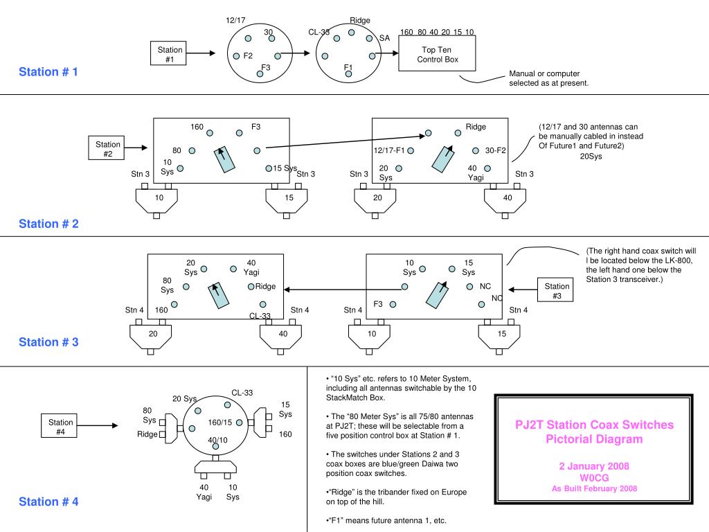
Explore the detailed setup of antennas at Ridge Station, including future antenna configurations, coax switches, and system controls for optimal signal reception. The as-built diagram provides a visual guide to the intricate setup at this station.
Comprehensive Control System for Antenna Array Setup at Ridge Station - slide 1
01 / 1Comprehensive Control System for Antenna Array Setup at Ridge Station
1 / 17

Télécharger la présentation

Comprehensive Control System for Antenna Array Setup at Ridge Station
Une image / un lien ci-dessous est fourni (tel quel) pour télécharger la présentation

Politique de téléchargement : le contenu du site vous est fourni TEL QUEL pour votre information et votre usage personnel ; il ne peut être vendu, concédé sous licence ni partagé sur d’autres sites sans l’accord de son auteur.Le contenu vous est fourni TEL QUEL, pour votre information et votre usage personnel uniquement. Téléchargez la présentation en cliquant sur ce lien. Lors du téléchargement, si vous ne parvenez pas à télécharger une présentation, l’éditeur a peut-être supprimé le fichier de son serveur.Pendant le téléchargement, si vous ne parvenez pas à obtenir une présentation, le fichier a peut-être été supprimé par l’éditeur.

F I N

Plus de contenu associé

Transcription de la présentation
  1. 12/17 Ridge 30 CL-33 160 80 40 20 15 10 SA Station #1 Top Ten Control Box F2 F3 F1 Station # 1 Manual or computer selected as at present. 160 F3 Ridge (12/17 and 30 antennas can be manually cabled in instead Of Future1 and Future2) Station #2 80 12/17-F1 30-F2 20Sys 10Sys 15 Sys 20 Sys 40 Yagi Stn 3 Stn 3 Stn 3 Stn 3 10 15 20 40 Station # 2 (The right hand coax switch willl be located below the LK-800,the left hand one below the Station 3 transceiver.) 20 Sys 40 Yagi 10 Sys 15 Sys 80Sys Ridge NC Station #3 NC F3 Stn 4 160 Stn 4 Stn 4 Stn 4 CL-33 20 40 10 15 Station # 3 • “10 Sys” etc. refers to 10 Meter System, including all antennas switchable by the 10 StackMatch Box. • The “80 Meter Sys” is all 75/80 antennas at PJ2T; these will be selectable from a five position control box at Station # 1. • The switches under Stations 2 and 3 coax boxes are blue/green Daiwa two position coax switches. • “Ridge” is the tribander fixed on Europe on top of the hill. • “F1” means future antenna 1, etc. CL-33 20 Sys 15 Sys 80 Sys Station #4 160/15 PJ2T Station Coax Switches Pictorial Diagram 2 January 2008 W0CG As Built February 2008 Ridge 160 40/10 40 Yagi 10 Sys Station # 4