Download
1 / 20
200 likes | 284 Vues
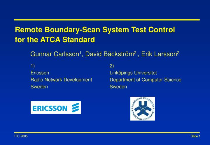
Remote Boundary-Scan System Test Control for the ATCA Standard. Gunnar Carlsson 1 , David Bäckström 2 , Erik Larsson 2. 1) Ericsson Radio Network Development Sweden. 2) Linköpings Universitet Department of Computer Science Sweden. Outline. Remote Boundary-Scan System Test Control

E N D
Remote Boundary-Scan System Test Control for the ATCA Standard Gunnar Carlsson1, David Bäckström2 , Erik Larsson2 1) Ericsson Radio Network Development Sweden 2) Linköpings Universitet Department of Computer Science Sweden
Outline Remote Boundary-Scan System Test Control for the ATCA Standard • Introduction • System Environment • Approach • Demonstration Board • Conclusions
Introduction • Boundary Scan (BScan) not only used for production interconnect test of boards • In multiboard systems the test controller and the target devices may be located on different boards • How to link BScan between controller and target devices? • Natural solution: BScan control and data must be routed through backplane Boundary Scan in Modern Systems
Introduction Multiboard Systems Application specific boards Backplane Shelf Management Board
Boundary Scan A T E Introduction System BScan Master/Slave BScan Multidrop Local BScan Master/Slave Control Path Central Processor Local Processor Local Processor Local Processor System Management Application Boards
Introduction Related Work • Several commercial solutions exist how to link BScan in a backplane environment • National Semiconductor: SCAN Bridge • Based upon: [D.Bhavsar, ITC´91] • Addressing boards and modules by using the instruction scan • Texas instruments: Addressable Shadow Port (ASP) • [L.Whetsel, ITC´92] • Added shadow protocol used to access boards and modules
Introduction Problem Definition • However, some system architectures do not include BScan in the backplane • The emerging ATCA standard is an example, which will be increasingly deployed • The purpose of this project is to find a way to manage remote BScan control in ATCA based systems
System Environment ATCA Overview • Advanced Telecommunications Computing Architecture (ATCA) • Contain design specifications and requirements in the following areas: • Mechanical and Dimensions • Power Distribution • Thermal Dissipation • Interfacing and Interconnections • System Management
System Environment • Intelligent Platform Management Interface (IPMI) • Exposing HW management functions to OS and Management SW • Provides interface and communications for: • Monitoring and Logging • Inventory • Recovery Control • Allows implementation of additional management applications within the IPMI framework System Management (IPMI)
System Environment System Management (IPMI) Management Bus (IPMB) Management SW/OS SM BMC BMC Shelf Management Board Application Board Application Board SM = Shelf Manager BMC = Baseboard Management Controller
Payload BMC to scale Payload Interface FRU LEDs Synch & Clock I/F Update Channel I/F Temperature Sensor Bussed E-Keying Enables 15 Point-to-Point E-Keying Enables Fabric I/F BMC Controller Bussed E-Keying Enables 1 IPMB-0 Buffers 1 Enable Blue LED Base I/F 16 Hardware Address [7:0] Power Supply Monitoring Payload Power Enable Management Power Metallic Test Bus IPMB-0 Hardware Address Dual –48V Power DC/DC Converter Monitor/ Controller Handle Switch
System Environment • Intelligent Platform Management Bus (IPMB) • Based on the two wire serial I2C Bus • Data transfers up to: 100 kbit/s • Maximum message size: 32 bytes • All IPMI messaging, including IPMB, uses a request/response protocol • All IPMB requests must be answered with an IPMB response • Requests and Responses are not automatically paired Management Bus (IPMB)
Approach • Propose a way to transport BScan data and control using the IPMB • Propose means how to manage embedded tests in IPMI • The solution should fit in the ATCA/IPMI context • Build a demonstration board to validate the proposed solution Project Goals
Approach New Functionality in IPMI IPMB Operator/ Test Program SM BMC Memory Memory Components under test Shelf Management Board Application Board
Approach • Command set to interface and control the onboard tests: • Test management commands: • LIST, SEND, RECEIVE, DELETE • Test execution commands: • RUN • Test setup commands: • LINK, OPTIONS • Embedded test data format • National Semiconductor EVF is an example • Based on the Serial Vector Format (SVF) Commands and Data Format
Approach • IPMB designed to carry short control and status messages • Extended the IPMB protocol to enable transport of BScan control and data • Still follows the rules and requirements set by the standard IPMB protocol • The SM unit is the requester (master) and the BMC units are the responders (slaves) • Mechanisms for dividing larger test files into smaller IPMB packages and re-assembling of packages back into test files has been specified and implemented Transport of BScan Control and Data
Approach Transport of BScan Control and Data • Transport times of a 77 kB EVF file on IPMB
Operator Interface SM Demonstration Board Demonstration Board Operator Interface UUT SM BMC BSC IPMB Shelf Manager Board Backplane Application Board
Demonstration Board Demonstration Board Operators interface UUT BMC-unit SM-unit BScan controller
Conclusions • Easy to add BScan functionality to the ATCA/IPMI context • IPMB suitable to carry BScan control and status • IPMB less suitable to carry large tests due to the limitations of the standard. • Can be solved using the higher available I2C data transfer speeds and larger IPMB packet sizes