Electronics Application Guide: Ohm's Law, Op-Amp, Relay, Sensors
Explore electronics fundamentals with Ohm's Law, potential dividers, resistors in series and parallel, operational amplifier applications, switches, relays, and diverse sensors. Learn to use components like transistors, diodes, variable resistors, relays, and operational amplifiers in circuits. Discover how to control music IC with a 9V battery, build a Darlington Pair, create a potential divider for motor control, and implement sensors like dark, moisture, and heat sensors for various applications. Enhance your knowledge of electronics principles and practical circuits with this detailed guide.

Electronics Application Guide: Ohm's Law, Op-Amp, Relay, Sensors
E N D
Presentation Transcript
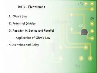
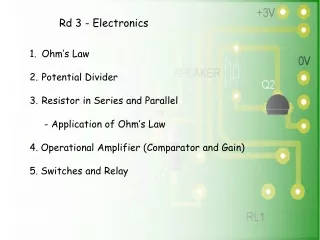
Rd 3 - Electronics • Ohm’s Law • Potential Divider • Resistor in Series and Parallel • - Application of Ohm’s Law • 4. Operational Amplifier (Comparator and Gain) • 5. Switches and Relay
Using Operational Amplifier to control Music IC 9V Battery 1 SPDT Switch Thermistor Variable Resistor 10K Resistor (*3) 3140 Op_amp TIP121 Transistor IN4148 Diode M66T Music IC 8 Ohm Speaker 3V Battery Connector 1 SPDT Relay 220uF Capacitor 9 Volt Circuit 3 Volt Music IC
Circuit Symbol 3140 Op-Amp An integrated circuit consisting of a silicon chip in a plastic 8 pin package Contains 20 transistors eleven resistors and one capacitor. Typical uses: - Voltage comparator, High gain amplifier
Op-Amp as a Comparator Compares the voltage at pin 2 to the voltage at pin 3 If V3 > V2 the output is high (on) If V3 < V2 the output is low (off) Voltage at pin 2 = threshold or reference voltage
Darlington Pair A special arrangement of two transistors (often called a DarlingtonPair) is shown in the diagram opposite. There are number of situations in which we might make use this configuration. What are the advantage of using an arrangement such as this? • It is much more sensitive • The TIP121 is a form of Darlington pair and can carry up to 1 amp of current. Most transistors carry 100mA • Only a tiny base current is needed as the gain is around 1000 • Note however that this transistor switches at 1.2V Why?
Potential Divider – DPDT motor control (Reversal) 9 Volt Battery Clip 3V Battery Clip 3 Terminal Blocks 1k resistor BC337 Transistor 1N4148 Diode Red LED 470 Ohm Resistor 1 DPDT relay 1 Toggle Switch 1 SPST Switch 2 Microswitches Motor
Variable Resistor Variable resistors consist of a resistance material with connections at both ends and a wiper which moves along the track as the arm is rotated through 270°. The track is normally rotary but straight track versions, usually called sliders, are sometimes used. The further clockwise the wiper is rotated, the larger the resistance.
T b T a P 1 P 2