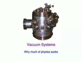
The Vacuum systems at GANIL The technical solutions and maintenance aspect P. Dolegieviez
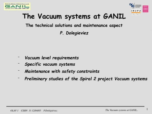
The Vacuum systems at GANIL The technical solutions and maintenance aspect P. Dolegieviez. Vacuum level requirements Specific vacuum systems Maintenance with safety constraints Preliminary studies of the Spiral 2 project Vacuum systems. For the beam Transmission

The Vacuum systems at GANIL The technical solutions and maintenance aspect P. Dolegieviez
E N D
Presentation Transcript
The Vacuum systems at GANIL The technical solutions and maintenance aspect P. Dolegieviez • Vacuum level requirements • Specific vacuum systems • Maintenance with safety constraints • Preliminary studies of the Spiral 2 project Vacuum systems
For the beam Transmission pressure values are determined to minimize beam losses due to charge exchanges between the ions and residual gas 10 m Vacuum level requirements TIS For the beam lines the average pressures 5.10-6 < P (Pa) < 5.10-5 For the cyclotrons P < 5.10-6 Pa and 2.10-6 Pa for SSC1 (determined for the heaviest ions)
Reducing the gas flow Systems are designed with low desorption rate materials and metallic seals Use of chimically cleaning processes High pumping speed (for the large cyclotron vessels) Dry pumping ( to avoid oil contamination on the high voltage elements) • Cryopumps with cryogenerator • turbopumps Ganil pumping configuration General choices
Main parameters of the vacuum chamber Diam. 9 m Weight 57 t Volume 46 m3 Specific vacuum systems : SSC Stainless steel 730 m2 Mild iron 160m2 Copper 240 m2 Elastomère seal 0,5 m2 Slippering mat. 2,2 m2 RF cavity
Specific metallic seals Section : 0.33 cm² Poids : 0.171 kg/m Matière : A5 recuit Dureté : 23 < Hv20g < 26
SSC Vacuum system 7 cryopumps (800 mm) 20m3.s-1 (N2) 10 m3.s-1 (H2) 1 cryopump (400 mm) 5 m3.s-1 (N2) (with valve) 4 turbopumps (400mm) 3,5 m3.s-1 (N2) (with valve) Roughting pumping syst. 2 x 2000 m3.h-1 (common to the cyclotrons) • Specific cryopump (800mm) • Cold sources 3x 12W @ 20K 35W @ 77K To optimise H2 pumping speed : 20K stage is in direct view of the chamber Specific vacuum systems : SSC
Compact cyclotron (RIB dedicated) integrated cryopanels to obtain the pumping speed required 30 m3.s-1 (N2) 40 m3.s-1 (H2) Specific vacuum systems : CIME • Cryopanels are cooled by cryofluids (LN2 , LH2) • Cryofluids are produced by cryogenerators
Specific vacuum systems : CIME Cime cryopumping system Designed by IPN- Orsay designed by CNRS/IPN-Orsay • 2 cryopanels (can run separately) • For each cryomodule : • 2x36W for N2 heat pipe -> 12Kg Cu @ 80K • 2x10W for H2 heat pipe -> 6.5Kg Cu @ 20K • 350g act. charcoal @ 20K
Specific vacuum systems : CIME performances 4.10-6 Pa after 24h P ultimate ~ 1. 10-6 Pa
Spiral 1 TIS ~ 8.1010 Bq in C target Contact : jardin@ganil.fr Specific vacuum systems for RIB facility Spiral 1 • TIS located in a concrete cave • A robot is used to remove the TIS after irradiation • vacuum equipments are located outside of the cave (except TMP) • Specifications for TMP • avoid electronics comp. • use EPDM o-rings (106 Gy)
Ganil today : no radioactive exhaust gas authorization to the atmosphere Nuclear ventilation TIS and LEBT High Vacuum flow are stored S q ~ 2. 10-3 mb.l.s-1 during 2 weeks • Filtration (HE filters) • Radiologic control (gaz and aerosol) • exhaust • Storage line • storage below atm. Pressure (-> 0.75 Pat) • confinment box (~ -10 Pa) • use magnetic coupling for rotary pumps • leak test before operation (He test) • flow control during production ( P fore-line) Specific vacuum systems for RIB facility Spiral 1 1 static + 2 dyn. barriers (during the filling up) A demand for radioactive exhaust gas is in progress (Spiral 2 project)
Safety legal requirements (RGE Ganil) Applied to the workers D < 1mSv/year and < 200 mSv/day Applied to maintenance procedures equipments are classified according areas All the equipements under the vacuum beam are classified MZC (potentially activated) • Particular procedures for the vacuum maintenance equipments must be applied • concerning the workers (medical control) • Necessity to follow (tracability) all components and the wastes generated by maintenance operations (solid and liquid) Maintenance with safety constraints
To guarantee the follow up of the procedures vacuum maintenance are executed on site • increase in the cost maintenance • subcontracted work on site • dedicated places and tools • evacuation of wastes by specialized firms Maintenance with safety constraints
Activity levels measured on vacuum equipments During maintenance operations significant activity levels concern mainly rotary pumps dedicated to the RIB production station D ~ 2 mSv/h after RIB production (78Kr@77 Mev/u -> C target) 0,35 mSv/h after 2 days of decay activity max measured in oil’s rotary pump A ~106 Bq/liter (g rays / long life period) radionucleis trapped in oil pumps constitute today the highest source of radioactivity to be treated during vacuum maintenance operations Maintenance with safety constraints
Production hall : critical area in terms of safety • vacuum syst. must allow also : • containement barriers of radioactive matter (static + dyn.) • miniminize transfert of RG through vacuum chambers Preliminary studies of the Spiral 2 project Vacuum systems concerning the RIB A ~ 6.1014 Bq in the U target with high radiotoxicity elements (a-emitters or iodine)
plug technology : to shield during operation and confine during maintenance operations Service cap and pumps Dcalc. < 200 m Gy/h Shielding block 70 cm concrete 50 cm ss balls Converter + TIS Preliminary studies of the Spiral 2 project Vacuum systems containement barriers Plug technology chosen (as for TRIUMF) for the converter, TIS, separator • after irradiation : isolated by valves and remotely transported to a shielded bunker • After sufficient storage time (>2 months) : transported into a hot cellfor maintenance via remote hand manipulators
vac. pumps vac. pump gasket primary pump insulator tank pump 10-6mbar supply pipe converter TIS 10-5mbar 10-7mbar output valve input valve vacuum-tight tank Preliminary studies of the Spiral 2 project Vacuum systems Configuration with Wien filter option as separator
Preliminary studies of the Spiral 2 project Vacuum systems Minimization of the radioactivity transfert through vacuum chambers : cryogenic traps to stop non-ionised elements ( prototype planned in 2005) To be install on the beam lines before and after the production hall Principle scheme
Today in Ganil the radioactive levels don’t induced failures for the vacuum system The dose rate during maintenance operations on the vacuum equipments are very low (<< Ganil requirements) The laboratory is organized to maintain the vacuum equipments on site The Spiral 2 project with its hard environment needs a different approach to design the vacuum system conclusion