Download
1 / 47
500 likes | 888 Vues
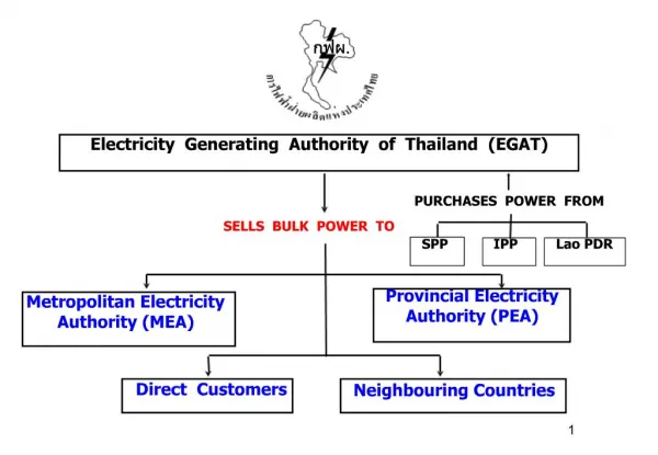
SHARJAH ELECTRICITY & WATER AUTHORITY. 2014. By : Asma ali Hajar Saeed Hessa elshiba noura ali Shaima Juma. What is SEWA ?. Sharjah Electricity And Water Authority (SEWA) is the providing services of electricity, water and natural gas to the residents of Sharjah city.

E N D
SHARJAH ELECTRICITY & WATER AUTHORITY 2014 By : Asma ali Hajar Saeed Hessa elshiba noura ali Shaima Juma
What is SEWA ? • Sharjah Electricity And Water Authority (SEWA) is the providing services of electricity, water and natural gas to the residents of Sharjah city. • It was established in the 1940 • SEWA contain many departments such as : • Electricity and Desalination Plants on Abu Moussa, Wasir Bu Nair and Al ZubairIslands • KhorfakkanElectricity Generation and Water Desalination Plant • ZulalWater Factory • Al Layyah Electricity Generation and Water Desalination
WasitElectricity Generation Plant • Generate electricity only • Contain 6 main departments • Administration department • Operation Room • Planning department • Electrical Maintenance Department (EMD) • Instrument Maintenance Department (IMD) • Mechanical Maintenance Department (MMD) • Two main ways to generate power • Diesel Power Generation • Gas Power Generation. • But other station can do also Steam Power Generation
Gas Turbine • Phases:. • Phase 1 • GT1, 2, 3 • Phase 2 • GT 4A,4B • Phase 3 • GT 5A, 5B • Phase 4 • GT 6A, 6B • Phase 5 • GT 7A, 7B • Two RoissRoiss • Total Power generated =1200 MW
Gas Turbine • Two type • Frame 6 (10 compaction unite, Start motor work on diesel) • Frame 9 (14 compaction unite, Start motor work on electrical) Frame 6 Frame 9
Gas Turbine • Component: • Filter • filtering the air from humidity and dust • Air dust • clean the air • Axial compressor • Increase air pressure • Combustion chamber • Increase the volume of air by heating it • Turbine • Convert the thermal energy of gases in mechanical energy (as useful work on the rotor) • Generator • generate the power from mechanical to electrical • Step up/ step down transformer • SU increase the power while SD decrease the power. • Starting Device • give power to unit to start
Gas Turbine • Elements for turbine running: • Cooling • reduce the temperature of gas • Supplying fuel • Such as gas or diesel • Atomizing air for combustion • Its used to convert the liquid fuel into small drops to go into the CC
Gas turbine • Starting the turbine: • Electrical motor or diesel engine to start the unit as the routine reach 60% so the combustion chambers are fired. • As the turbine speed is higher than the start engine speed the engine is disconnected and shut down. • As the turbine reach the nominal speed, the unit is ready to be synchronized to the network so the starting is complete and the unit has reach full speed no load (FSNL).
Gas turbine • Shutting Down: • Normal shutdown • Manually operation by stop switch or some mechanical or regulation problem through protection devices • Emergency shutdown (Trip) • Depressing the emergency stop button or by some mechanical or regulation important problem through special devices. • Trip is for two reason • Human error • Protection • Actual (Ex. problem in the Vibration device) • False (Ex. wrong reading from the Vibration device)
Cooling water System 3 1 4 2
Cooling water System process • The water is stored in the tank which is distilled water • The motor move the distilled water to two parts. • Generator • Oil temperature cooling and then to the atomizing air cooling So it will reduce the temperature for the two parts • The water is joined from the two part and then go to the fans. • The fans reduce the water temperature
This step is Immediately following a shut down Cooling down • The turbine can be: • Started • loaded at any time during the cooling down cycle. The rotor is rotated to provide uniform cooling. prevents rotor from bowing, rubbing and imbalance.
Cool down operation: Start up : cool down on.( + execute). auxiliary oil pump AOP stars ( checks oil pressure 7 bar) lube oil heater pressure 1.3 bar. cooling water pump start ( pressure 4 bar). jacking oil pressure: 80 -100 bar. mist eliminator fan starts. BT fan will start. check the oil flow in all the view glass
Exhaust System The Exhaust systems have a fan. Exhaust systems are necessary to guide the exhaust flue gases and the toxic gasesof the gas turbine into the atmosphere. It can cause to death.
Fire fighting system Most fires happens because of diesel leaking.
Generating Sequence F-6 2x33MW – 11KV 8x10⁹MW – 15KV F-9 RR 2x47MW – 11.5KV BE TY 1x23MW – 11KV Monitoring Frequency 50 Hz 400 V 230 V
Wasit Distribution Network SAJA1 SAJA2 SAJA3 SAJA4 X X X X 220 KV X 143 MVA X 15/220 KV 282 MVA 302 MVA X X X X X X IB 220/132 KV ~ ~ ~ ~ ~ ~ ~ ~ ~ GT 4B GT 5A GT 4A GT 5B X X ~ ~ ~ ~ GT 7B GT 7A GT 6A 15 KV 100MW GT 6B 2x75 MVA 15/ 6.6 KV 4MVA X 132 KV X X X IB 220/33 KV X X X X X X X X X X X X X 3x75 MVA 33 KV X X X X X X GT1 30 MW GT2 30 MW GT3 20MW RR1 40MW RR2 40MW RMTA UMKR AZRA GHFA RMQ Generator 220 KV 132 KV 33KV
Transformers Oil Filed Dry type High capacity Low Capacity For Volt Transfer
Monitoring Start up Protection Monthly Maintenance Average cost No Maintenance Highest cost Yearly Maintenance Cheap
Mechanical Maintenance Departments (MMD) MMD: design and manufacturing, and installation, and operation of the engines, machinery, and manufacturing processes.
Gas system operation • The two main valves : • GCV: set for gas control valve. • SRV: set for gas ratio valve. • Operation: • Gas come from SAJAA (yellow pipe) and goes directly to SRV & GCV , which take the gas to combustion chamber if they open. If any trip happen they will close and solenoid gas valve open to let the gas which located between them to go to the atmosphere.
Torque Converter operation • Two motor to rotate the shaft: • Turbine gear motor (88TG – 1, Turning gear) • Cranking motor (88CR– 1) • The torque converter transfer the speed from left side shaft to the right side shaft, if the left is running in 1000 rpm then the right should run at the same speed. • Inside the torque converter there is two main things that transfer the speed between the motors • Solenoid valve turbine unit (20TU – 1) • Limit switch turbine control (33TC – 1) • Both this thing are operate using oil wine the oil pass throw them they are connected and the operation starts.
IGV operation • IGV located before the compressor it take the air from filter and send 100% pure air which has no dust or moisture for compressor. If the IGV open with 34 degree it has zero loads (zero speed) the turbine not rotating. When the degree reaches 56 degree the chamber is firing this mean that it’s full speed with 3000 rpm.
IMD: reading the valves from the Gages Instrument Maintenance Departments (IMD) is a converter that measures a physical quantity and converts it into a signal Sensors that detect the presence of operators near hazardous machines of facilitates. measure temperature by correlating the resistance of the RTD element with temperature. Measure the temperature How many rpm Detect the level of the valve Indicate the position of the valve Detect the gas
GCV and SRV instruments • GCV • Solenoid valve fuel gas control (20FGC – 1) • SRV • Solenoid valve fuel gas start (20FGS – 1) • Solenoid valve gas (20VG – 1) • Release the gas that is between SRV & GCV • Pressure Transmitter fuel gas • To detect the gas pressure • 96FG – 2A • 96FG – 2B • 96FG – 2C
Load Dispatch Center (LDC) Supervise control and data equation
Fiber optic definition Advantage Fiber optic cables have a much greater bandwidth than metal cables. This means that they can carry more data. Fiber optic cables are less susceptible than metal cables to interference. Fiber optic cables are much thinner and lighter than metal wires. Data can be transmitted digitally (the natural form for computer data) rather than analogically. • The medium and the technology associated with the transmission of information as light impulses along a glass or plastic wire or fiber.
RTU (Remote Terminal Unit) definition types PDH (Plesiochronousdigital hierarchy) 2 Mbps telecommunications network transmission technology designed for the transport of large data volumes across large scale digital networks. PDH uses ( E1) channels in Europe and 1.544 Mb/s ( DS1) channels in the US and Japan. Each E1 = 64Kbps • an electronic device that is controlled by a microprocessor. • The device interfaces with physical objects to a Distributed Control System (DCS) or Supervisory Control and Data Acquisition (SCADA) system by transmitting telemetry data to the system.
RTU (Remote Terminal Unit) types SDH’s benefits over the pdh Reduce costs world standard digital format synchronous structure is flexible Easy traffic cross connection capacity and add and drop facility • SDH (Synchronous Digital Hierarchy) • standard technology for synchronous data transmission on optical media. It is the international equivalent of Synchronous Optical Network. • Synchronous Transport Modules (STM) • STM-1 (155 Mbps) = 63*E1 • DWDM (Dense wavelength division multiplexing)
SCADA (Supervisory Control and Data Acquisition) definition SCADA systems include hardware and software components. The hardware gathers and feeds data into a computer that has SCADA software installed. The computer then processes this data and presents it in a timely manner. SCADA also records and logs all events into a file stored on a hard disk or sends them to a printer. SCADA warns when conditions become hazardous by sounding alarms. • Acategory of software application program for process control, the gathering of data in real time from remote locations in order to control equipment and conditions • Used to monitor and control a plant or equipment in industries such • telecommunications • water and waste control • energy • oil and gas refining and transportation