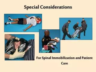
Special Design and Construction Considerations
Special Design and Construction Considerations. 2009 PDCA Professor Pile Institute. Patrick Hannigan GRL Engineers, Inc. SPECIAL DESIGN CONSIDERATIONS. Time effects on pile capacity. Pile driveability Scour Densification effects on pile capacity

Special Design and Construction Considerations
E N D
Presentation Transcript
Special Design and Construction Considerations 2009 PDCA Professor Pile Institute Patrick Hannigan GRL Engineers, Inc.
SPECIAL DESIGN CONSIDERATIONS • Time effects on pile capacity. • Pile driveability • Scour • Densification effects on pile capacity • Additional design and construction topics in FHWA Pile Manual Chapters 9.9 and 9.10
590 560 530 500 14” CEP 470 430
TIME EFFECTS ON PILE CAPACITY Time dependent changes in pile capacity occur with time. Soil Setup Relaxation
SOIL SETUP Soil setup is a time dependent increase in the static pile capacity. Large excess positive pore pressures are often generated during pile driving. Soil setup frequently occurs for piles driven in saturated clays as well as loose to medium dense silts and fine sands as the excess pore pressures dissipate. The magnitude of soil setup depends on soil characteristics as well as the pile material and type.
Soil Setup 1 day 10 days 100 days 1000 days Semilog-linear process Restrike testing generally performed 1 to 10 days after installation When to test? capacity Economically desirable Technically desirable log time
SOIL SETUP FACTOR The soil setup factor is defined as failure load determined from a static load test divided by the ultimate capacity at the end of driving.
RELAXATION Relaxation is a time dependent decrease in the static pile capacity. During pile driving, dense soils may dilate thereby generating negative pore pressures and temporarily higher soil resistance. Relaxation has been observed for piles driven in dense, saturated non-cohesive silts, fine sands, and some shales.
RELAXATION FACTOR The relaxation factor is defined as failure load determined from a static load test divided by the ultimate capacity at the end of driving. Relaxation factors of 0.5 to 0.9 have been reported in case histories of piles in shales. Relaxation factors of 0.5 and 0.8 have been observed in dense sands and extremely dense silts, respectively.
TIME EFFECTS ON PILE DRIVEABILITY AND CAPACITY Time dependent soil strength changes that affect the soil resistance at the time of driving should be considered during the design stage. • Remolded shear strength in clays • Estimate of pore pressures during driving • Soil setup / relaxation factors
PILE DRIVEABILITY Pile driveability refers to the ability of a pile to be driven to the desired depth and / or capacity at a reasonable driving resistance without exceeding the material driving stress limits.
Soil Profile Illustrating Driveability Considerations Estimated Tip EL 14” Pipe Estimated Tip EL 12” H-pile
FACTORS AFFECTING PILE DRIVEABILITY • Driving system characteristics • Pile material strength • Pile impedance, EA/C • Dynamic soil response Primary factor controlling driveability
PILE DRIVEABILITY Pile driveability should be checked during the design stage for all driven piles. Pile driveability is particularly critical for closed end pipe piles.
PILE DRIVEABILITY EVALUATION DURING DESIGN STAGE 1. Wave Equation Analysis Computer analysis that does not require a pile to be driven. 2. Dynamic Testing and Analysis Requires a pile to be driven and dynamically tested. 3. Static Load Tests Requires a pile to be driven and statically load tested.
3 ft • Silty Clay • = 127 lbs / ft3 qu = 5.5 ksf 46 ft • Dense, Silty F-M Sand • = 120 lbs / ft3 = 35˚ 20 ft Soil Profile – 12.75 In CEP
Student Exercise #2 Revisited Static analysis indicates a 12.75 in O.D. closed-end pipe pile driven to 63 ft below grade can develop an ultimate capacity of 420 kips. A static load test will be used for construction control. No special design conditions exist (scour, downdrag, etc.). Therefore, a maximum axial design load of _______ kips can be used. 210
Pick Pile Section – (Appendix C2-4) Given: 12.75 in O.D. closed-end pipe pile Select: wall thickness – try 0.109 in wall (lowest cost) ASTM A-252 Grade 3 steel – FY = 45 ksi 28 day concrete strength – f’c = 5 ksi
Check Allowable Design Load (10-5) Design Load = 0.25 (FY)(steel area) + 0.40(f’c)(concrete area) = 0.25(45 ksi)(4.33 in2) + 0.40(5 ksi)(123.0 in2) = 48.7 kips + 246.0 kips = 294 kips Is this section suitable for an 420 kip ultimate pile capacity? ____ Yes
Check Pile Driveability Driveability Requirements: Driving resistance between ____ and ____ blows/ft (see pg 11-15) Driving stress limit of 0.9(FY) = _____ ksi (see pg 10-5) 30 120 40.5
Check Pile Driveability Determine Hammer Size: Rated energy for 420 kip ultimate capacity ____ ft-kips (see pg 21-36) Select trial hammer __________________________ (see Appendix D-1) Perform Wave Equation Analysis 38 Delmag D-16-32 (ID #5)
GRLWEAP Driveability Results For D-16-32
Piles Subject to Scour Types of Scour Aggradation / Degradation Scour - Long-term stream bed elevation changes Local Scour - Removal of material from immediate vicinity of foundation Contraction and General Scour - Erosion across all or most of channel width
Pile Design Recommendations in Soils Subject to Scour • Reevaluate foundation design relative to pile length, number, size and type • Design piles for additional lateral restraint and column action due to increase in unsupported length • Local scour holes may overlap, in which case scour depth is indeterminate and may be deeper.
Pile Design Recommendations in Soils Subject to Scour 4. Perform design assuming all material above scour line has been removed. 5. Place top of footing or cap below long-term scour depth to minimize flood flow obstruction. 6. Piles supporting stub abutments in embankments should be driven below the thalweg elevation.
Densification Effects on Pile Capacity Densification can result in the pile capacity as well as the pile penetration resistance to driving being significantly greater than that calculated for a single pile. Added confinement from cofferdams or the sequence of pile installation can further aggravate a densification problem.
Densification Effects on Pile Capacity Potential densification effects should be considered in the design stage. Studies indicate an increase in soil friction angle of up to 4˚ would not be uncommon for piles in loose to medium dense sands. A lesser increase in friction angle would be expected in dense sands or cohesionless soils with a significant fine content.
Pile Driving Induced Vibrations Vibrations from pile driving sometimes perceived as a problem. Vibrations can cause damage. Vibrations can cause soil densification and settlement. Pile driving vibrations often a perceived problem than an actual problem and can often be controlled by construction procedures PDCA database – www.piledrivers.org
Charleston SC Project • 220 piles monitored • 2 failed vibration criteria • No significant movement (> 1 mm) recorded by crack monitoring devices • No damage to masonry facade • Hydraulic hammer (30 ft-kip) • HP 12 x53 H-piles • Predrill 12” diameter hole to 40 ft.