Download

1 / 29
290 likes | 317 Vues
This study presents results from a simultaneous PET-MRI breast scanner, detailing prototype design, clinical protocols, and preliminary results. It highlights the importance of image analysis in utilizing PET and MRI data effectively. Future directions include larger prototypes and improved lesion characterization. Acknowledgements and support are also mentioned, emphasizing collaborative efforts in this groundbreaking research.

E N D
Results from a Simultaneous PET-MRI Breast Scanner Bosky Ravindranath1, Sachin Junnarkar2, Martin Purschke2, Sean Stoll2, Xiaole Hong3, Pai-Jung Huang4, Sri Harsha Maramraju1, Paul Vaska2, Craig Woody2, David Schlyer2 1Biomedical Engineering, Stony Brook University, Stony Brook, NY, 2Brookhaven National Laboratory, Upton, NY, 3Aurora Imaging Technology, Inc., North Andover, MA, 4Taipei Medical University Hospital, Taipei, Taiwan.
RF Coil Patient positioned with Breast PET insert & Aurora Breast RF coil Breast PET Insert Simultaneous PET-MRI Breast Imaging Aurora Dedicated 1.5 T Breast MRI
Prototype System Design An extension of the RatCAP technology To signal processing board 1:1 coupling between crystal and APD • 24 detector blocks • 2.2 x 2.2 x 15 mm3 LYSO (4 x 8 array) • Hamamatsu S8550 APD (4 x 8 array) • ID : ~ 10 cm • Axial extent : 1.8 cm
Clinical Prototype Need larger ID and flexibility in axial coverage ID ~ 11cm 24 detector PET ring with a crystal wide gap on either side PET ring is assembled in a plastic housing
Prototype PET Characteristics 0.25 mm diameter 22Na point source • Coincidence sensitivity of ~ 1% • Energy resolution: 13% • Simultaneous PET-MRI - • Good MRI compatibility, minimal effect on MRI • PET- increase in count rates during RF pulsing periods - can be gated out
PET Marker and Gamma Shielding PET marker Gamma Shielding Lead glass MRI image of breast with PET ring in FOV
Translation Mechanism • A translation mechanism was built for better axial coverage • Up/Down movement and angular positioning of PET ring • Can be positioned against chest wall • Supports gamma shielding of PET ring - lead glass, tungsten composite sheets
Clinical Protocol - Taipei Medical University Hospital Routine Breast MRI to find any lesions 18F-FDG Whole Body Scan* (supine position) Chest PET scan* (prone position) Simultaneous PET/MRI Delay phase prone PET* Biopsy * Scans done on Siemens Accel
Malignant-like Enhancement Washout Normal
Benign Enhancement Pattern Progressive (monophasic) Normal
Patient 1- whole body PET Tumor Tumor Bladder
Patient 1 - Simultaneous PET-MRI Transverse Sagittal Coronal MRI (RODEO) PET Simultaneous PET-MRI
Patient 3 - Sequential PET-MRI Subject 3 - : 8.67 mCi injection : Silicone Implant
Patient 3 Breast PET on Clinical Scanner Clinical PET images Our PET/MRI images
Future Directions • Next generation is considerably larger both in radius and in length increasing our field of view • This new deign has only three cables coming out 1 power and 2 optical fibers • The kinetics of both the contrast agent washout and the FDG washout are being combined to try and develop a better predictor of lesion type and aggressiveness
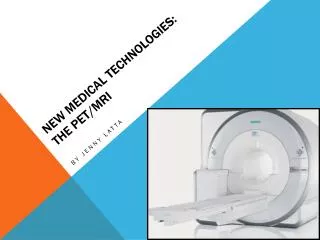
Things to Remember • The power of PET and MRI lies in the ability to analyze the images, not in making nice pictures • Think about kinetics as a way to better utilize PET and MRI data • Think about ways to retrofit the 30,000 MR scanners in the world to make PET/MR available for the clinic
Acknowledgements • Dr. P.J. Huang, TMUH • Dr. Hsu, TMUH • Dr. Xiaole Hong, Aurora Imaging Technology • Dr. David Bennett, Aurora Imaging Technology • Dr. Ken Cheng, Aurora Imaging Technology • Olivia Cheng, Aurora Imaging Technology • The Aurora and TMUH team of technologists and nurses who have provided support for this study • Dr. David Schlyer, BNL • Dr. Paul Vaska, BNL • Dr. Craig Woody, BNL • Dr. Sachin Junnarkar • Dr. Sri Harsha Maramraju, SBU • Sean Stoll, BNL • Dr. Martin Purschke, BNL • Bill Lenz, BNL • Richard Ruggiero, BNL • Dr. Gene-Jack Wang, BNL • Dr. Dardo Tomasi, BNL This work was supported by the U.S. Department of Energy (OBER) and Aurora Imaging Technology under Prime Contract No. DE-AC02-98CH10886.
Thank You Thanks to the BNL LDRD program, DOE and Aurora Imaging Technologies for Support of this work
Future Directions mm Prototype of circular motherboard • A full scale prototype construction is underway ( BNL, University of Pennsylvania)
MRI Sequential PET Sequential PET-MRI Subject 3 - : 8.67 mCi injection : Silicone Implant Preliminary Results Transverse Sagittal Coronal
Points to Remember • A proof of concept simultaneous PET/MRI study was conducted with 4 patients with biopsy proven or highly suspicious breast cancer • This is the first time a study of such kind has been carried out in breast cancer patients • This study lays the groundwork for a better understanding of the challenges of simultaneous PET/MRI within the patient population
Gamma Shielding PET System in the MRI • Shielding PET scanner inside the MRI FOV is challenging - introducing metal will cause susceptibility artifacts • Two types of shielding material were evaluated • Lead glass : • Lead glass sheets of 6 mm thickness were cut to the shape of the PET ring • Lead glass caused no artifacts in the MRI image • However, the thickness of the lead glass prevents bringing the PET scanner as close to the chest wall as possible, hence alternative higher density material was evaluated • Tungsten composite: • Six 1 mm thick sheets of tungsten composite material were made • Artifacts were evaluated by stacking them together • Susceptibility artifacts were present - hence use of only 1 sheet was deemed acceptable for use in those cases where the scanner needs to be against patient chest wall for best lesion coverage
Image Reconstruction and Data Correction • Image reconstruction is carried out using the Maximum Likelihood Expectation Maximization technique • The gaps between the crystals and the missing detector block are accounted for during reconstruction • System matrix estimation using SIMSET involved accurate modeling of the crystal position within the ring, the field of view of the PET scanner is further divided into ~ 1mm3 voxels and decays are simulated in each voxel. • Variation in detector efficiency is measured by acquiring uniform phantom data at the operating threshold voltage and gain settings and is fed into the reconstruction algorithm for applying corrections • Randoms fraction is estimated using delayed window technique • Normalization for correcting variation in detector efficiency is applied by measuring system response to a uniform phantom under operating conditions
Simulation in SIMSET 11C scan using prototype 4.0 1.6 1.2 4.8 4.8 3.2 2.4 1.2 4.0 2.4 3.2 1.6 Mini Deluxe Phantom ( Data Spectrum Inc., NC, USA)