Download
1 / 26
260 likes | 317 Vues
Learn about LG's Voice over IP (VoIP) and ISDN networking solutions for seamless inter-office communication. Detailed features like Net Call, Net Call Transfer, and Name Display ensure a unified communication experience.

E N D
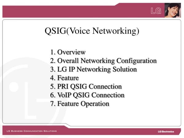
QSIG(Voice Networking) 1.Overview 2. Overall Networking Configuration 3. LG IP Networking Solution 4. Feature 5. PRI QSIG Connection 6. VoIP QSIG Connection 7. Feature Operation
1. Overview • LDK Voice networking provides a way of communication to inter-work with networked system over Internet(VoIP) or ISDN. • LDK provides uniform numbering plan for all users in the network • The networked systems can be considered as one system. • Extension in any system can talk with other system like extension call • Up to 72 systems can be inter-working via public or private network • LDK supports the total solution from Home office to Headquarter office with LG Systems (IP LDK-100/300/300E, IP LDK-20, NEXER and IPECS) 1/19
2. Overall Networking Configuration ISDN PRI & IP Network 2/19
RSG LDK-300/300E DSL or Cable Modem Router Home Office BLF Manager Headquarter Office IP Network NEXER Small Branch Office LDK-100 Router LIK-300 Router Branch Office Local Main Office 3. LG IP Networking Solution 3/19
4. Feature • The Following QSIG Features are provided • Net Call • Net Call Transfer (Screen / Unscreened) • Net Call Forward (Unconditional / Busy / No Answer / Busy No Answer) • Name Display • Call Offer(Camp-On) • Message Waiting Indication (MWI by Request) • Call Completion (Call Back) • CO Transit-In/Out • Calling Line Identification(CLI) • DECT Mobility • Absent Text Message Service • Do Not Disturb (DND) Service • Centralized Attendant Service (CAS) • Busy Lamp Field (BLF) Service • Centralized SMDR • Centralized VMS 4/19
5. PRI QSIG Connection Network Configuration • A Sample of QSIG Connection via ISDN PRI ISDN Master Slave P R I B M P B P R I B M P B STA NO 100 ~ 199 STA NO 200 ~ 299 NT mode TE mode LAN Minimum Requirements: 1. 2 PRIB cards 2. QSIG Lock Key for each system Additional Requirements 1. LANU of MPB 2. PC for BLF Manager 3. HUB and IP Address for IP Connection BLF Manager 5/19
5. PRI QSIG Connection Basic Programming Master System Slave System Station Number 1. Station range: 100~199 2. MPB IP Address: 192.168.23.10 3. CO Line type : Type 3(ISDN DID) 4. DID Conversion Type : Type 1 5. Networking Table PGM320 BTN 1 : Net Enable PGM321 BTN 4 (BLF MGR) : 192.168.23. 20 PGM322 (Net CO) BTN 1 : Net CO Group = 01 BTN 4 : Net CO Type = NET PGM324 BIN 00 (Master, itself) BTN 1 (Usage) = NET BTN 2 (STA Number) = 1#** BTN 3 (Net CO Gr) = 00 BIN 01 (Slave system) BTN 1 (Usage) = NET BTN 2 (STA Number) = 2** BTN 3 (Net CO Gr) = 01 BTN 4 (CPN) = Empty 1. Station range: 200~299 2. MPB IP Address: 192.168.23.11 3. CO Line type : Type 3(ISDN DID) 4. DID Conversion Type : Type 1 5. Networking Table PGM320 BTN 1 : Net Enable PGM321 BTN 4 (BLF MGR) : 192.168.23. 20 PGM322 (Net CO) BTN 1 : Net CO Group = 01 BTN 4 : Net CO Type = NET PGM324 BIN 00 (Slave, itself) BTN 1 (Usage) = NET BTN 2 (STA Number) = 2#** BTN 3 (Net CO Gr) = 00 BIN 01 (Master system) BTN 1 (Usage) = NET BTN 2 (STA Number) = 1** BTN 3 (Net CO Gr) = 01 BTN 4 (CPN) = Empty For BLF Service PRIB for Net Path PRIB for Net Path NET or PSTN Own STA number CO doesn’t need Net for Net Call PSTN for Transit Refer to PGM322 Direct connection Note: Each system in Networking range should have its corresponding programming like the above. 6/19
6. VoIP QSIG Connection Network Configuration • VoIP Connection between Systems Master Slave V O I B M P B V O I B M P B STA NO 100 ~ 199 STA NO 200 ~ 299 LAN Minimum Requirements: 1. 2 VOIB cards 2. IP Networking Lock Key for each system 3. Hub and IP Address for IP Connection Additional Requirements 1. LANU of MPB 2. PC for BLF Manager BLF Manager 7/19
6. VoIP QSIG Connection Basic Programming Master System Slave System Station Number 1. Station range : 100~199 2. MPB IP Address : 192.168.23.10 3. VoIB IP Address : 192.168.23.21 4. CO Line type : Type 3(ISDN DID) 5. DID Conversion Type : Type 1 6. Networking Table PGM320 BTN 1 : Net Enable PGM321 BTN 4 (BLF MGR) : 192.168.23. 20 PGM322 (Net CO) BTN 1 : Net CO Group = 01 BTN 4 : Net CO Type = NET PGM324 BIN 00 (Master, itself) BTN 1 (Usage) = NET BTN 2 (STA Number) = 1#** BTN 3 (Net CO Gr) = 00 BIN 01 (Slave system) BTN 1 (Usage) = NET BTN 2 (STA Number) = 2** BTN 3 (Net CO Gr) = 01 BTN 4 (CPN) = 192.168.23.22 1. Station range : 200~299 2. MPB IP Address : 192.168.23.11 3. VoIB IP Address : 192.168.23.22 4. CO Line type : Type 3(ISDN DID) 5. DID Conversion Type : Type 1 6. Networking Table PGM320 BTN 1 : Net Enable PGM321 BTN 4 (BLF MGR) : 192.168.23. 20 PGM322 (Net CO) BTN 1 : Net CO Group = 01 BTN 4 : Net CO Type = NET PGM324 BIN 00 (Slave, itself) BTN 1 (Usage) = NET BTN 2 (STA Number) = 2#** BTN 3 (Net CO Gr) = 00 BIN 01 (Master system) BTN 1 (Usage) = NET BTN 2 (STA Number) = 1** BTN 3 (Net CO Gr) = 01 BTN 4 (CPN) = 192.168.23.21 For BLF Service VoIP line for Net Path PRIB for Net Path NET or PSTN Own STA number CO doesn’t need Net for Net Call PSTN for Transit Refer to PGM322 IP address 8/19
7. Feature Operation Net Call [Call Flow] [Admin Programming] ■ Networking Basic Attribute : PGM 320 ■ Networking CO Line Attribute : PGM 322 ■ Networking Routing Table : PGM 324 Note : During conversation, all telephony features are available.(For example, call transfer, hold, conference and etc.) 9/19
Step 1 ~ 2 PSTN or ISDN Step 6 Step 3 Internet 100 Step 4 Step 5 202 7. Feature Operation Net Call Transfer [Call Flow] [Admin Programming] ■ Networking Basic Attribute : PGM 320 ■ Networking Transfer Mode : PGM 321-FLEX1 ■ Networking CO Line Attribute : PGM 322 ■ Networking Routing Table : PGM 324 10/19
Step 2 PSTN or ISDN Step 5 Step 1 Internet 100 Step 3 202 Step 4 7. Feature Operation Net Call Forward [Call Flow] [Admin Programming] ■ Call Forward Attribute : PGM 111-FLEX2 ■ Networking Basic Attribute : PGM 320 ■ Networking Transfer Mode : PGM 321-FLEX1 ■ Networking CO Line Attribute : PGM 322 ■ Networking Routing Table : PGM 324 11/19
Internet Step 1 Step 2 Step 3 100 Step 5 BUSY 202 Step 4 7. Feature Operation Call Offer [Call Flow] [Admin Programming] ■ Networking Basic Attribute : PGM 320 12/19
Step 1 Step 2 Internet Step 3 100 Step 4 Step 5 BUSY 202 7. Feature Operation Call Completion [Call Flow] [Admin Programming] ■ Networking Basic Attribute : PGM 320-FLEX8 13/19
Step 1 PSTN or ISDN Step 2 Step 5 Internet Step 3 Additional Programming Master : PGM 143 FLEX 4 (DID Conversion Type) = 2 PGM 231 (Flexible DID Table) = Assign Slave extension Step 4 202 7. Feature Operation CO Transit-In [Call Flow] [Admin Programming] ■ Networking Routing Table : PGM 324 14/19
Additional Programming Slave : PGM 324 BIN 10 -FLEX 1 (Usage) = PSTN -FLEX 2 (Net Code) = 9 (transit code) Delete 1st CO Group access code -FLEX 3 (Net CO Group) = 01 -FLEX 4 (CPN) = 192.168.23.21 -FLEX 7 (DGT Repeat) = YES Step 4 PSTN or ISDN Step 3 Internet Step 5 Step 2 Additional Programming Master : PGM 322 BTN 1 (Net Col Group) = 02 for PSTN Lines BTN 4 (Net CO Type) = PSTN PGM 324 BIN 10 -FLEX 1 (Usage) = PSTN -FLEX 2 (Net Code) = 9 (transit code) Delete 1st CO Group access code -FLEX 3 (Net CO Group) = 02 202 Step 1 7. Feature Operation CO Transit-Out [Call Flow] [Admin Programming] ■ Networking CO Line Type : PGM 322-FLEX2 ■ Networking Routing Table : PGM 324 15/19
100 Internet Step 2 BUSY Step 1 202 BLF Manager 7. Feature Operation BLF Service [Call Flow] [Application] ■ BLF Manager Software(PC Application) [Admin Programming] ■ Networking Supplementary Attribute : PGM 321 - TCP Port Assign(FLEX2) - UDP Port Assign(FLEX3) - BLF Manager IP Address Assign(FLEX4) - Duration of BLF Status(FLEX5) ■ Networking Routing Table : PGM 324 16/19
7. Feature Operation DECT Mobility [Call Flow] PSTN or ISDN Internet Additional Programming The WHTU should be registered both systems and the physical port number of WHTU should be same on whole systems. Master : PGM 324 BIN 01 - BTN 6(MPB IP Address)assign MPB IP address of slave Slave : PGM 324 BIN 01 - BTN 6(MPB IP Address)assign MPB IP address of master 17/19
LDK-A (Master) CAS Dial ATD Call Dial ATD Call LDK-B (Slave) LDK-D (Slave) Internet Or ISDN Dial ATD Call LDK-C (Slave) CO LINE 7. Feature Operation CAS The attendant call from a station of any networking system can be routed to the CA (Centralized Attendant) of CAS master system. From the other networking systems, if a station dials the attendant call code, then the call is routed to the centralized attendant station of LDK-A. [Admin Programming] ■ Networking CAS Enable : PGM 320 – FLEX6 ■ Attendant DND Button : PGM 115 – STA PGM Button(Type6) : 55 ■ Net Attendant Assign : PGM 164 – Net DSS cannot be assigned to the System Attendant. ■ DID/DISA Destination : PGM 167 ■ CO Ring Assignment : PGM 144 18/19
Demo & Practice • Net Call • Net Call Transfer (Screen / Unscreened) • Net Call Forward (Unconditional / Busy / No Answer / Busy No Answer) • Name Display • Call Offer(Camp-On) • Message Waiting Indication (MWI by Request) • Call Completion (Call Back) • CO Transit-In/Out • Calling Line Identification(CLI) • Absent Text Message Service • Do Not Disturb (DND) Service • Centralized Attendant Service (CAS) • Busy Lamp Field (BLF) Service • Centralized SMDR/VMS 19/19
PSTN D T I B S L I B L C O B P R I B V O I B M I S B M P B D T I B S L I B L C O B P R I B M P B 2000 2001 2012 . . 3000 3001 3012 . . 1000 1001 1012 . . D T I B S L I B V O I B M P B Internet WAN (A) LDK-100(1***) (B) LDK-300(2***) (C) LDK-300(3***) ■ MPB IP : 150.150.60.158 ■ VOIB IP : 0. 0. 0. 0 ■ PRIB(A↔B) ■ CO Group Setting - PRIB 005~034(NET CO : 01 ) - LCOB 001~004(NET CO : 02 ) ■ MPB IP : 150.150.60.159 ■ VOIB IP : 150.150.60.200 ■ PRIB(B↔A) ■ VOIB(B↔C) ■ CO Group Setting - PRIB 005~034(NET CO : 01 ) - VOIB 035~042(NET CO : 02 ) - LCOB 001~004(NET CO : 03 ) ■ MPB IP : 150.150.60.160 ■ VOIB IP : 150.150.60.201 ■ VOIB(C↔B) ■ CO Group Setting - VOIB 035~042(NET CO : 01 )
PSTN D T I B S L I B L C O B P R I B V O I B M I S B M P B D T I B S L I B L C O B P R I B M P B 2000 2001 2012 . . 3000 3001 3012 . . 1000 1001 1012 . . D T I B S L I B V O I B M P B Internet WAN (A) LDK-100(1***) (B) LDK-300(2***) (C) LDK-300(3***) • MPB IP : 150.150. 60.158 • VOIB IP : 0. 0. 0. 0 • [Admin Programming] • PGM320-BTN1 NET ENABLE : ON • PGM322-BTN1 NET CO GRP : 01/02 • PGM322-BTN4 NET CO TYPE : NET/PSTN • PGM324 NET NUM PLAY TABLE • - 00 : NET 1#*** (00) • - 01 : NET 2*** (01) • 02 : NET 3*** (01) • - 03 : PSTN/77 (02) Digit Repeat : Yes • MPB IP : 150.150. 60.159 • VOIB IP : 150.150. 60.200 • [Admin Programming] • PGM320-BTN1 NET ENABLE : ON • PGM322-BTN1 NET CO GRP : 01/02/03 • PGM322-BTN4 NET CO TYPE : NET/NET/PSTN • PGM324 NET NUM PLAY TABLE • - 00 : NET 2#*** (00) • 01 : NET 1*** (01) • 02 : NET 3*** (02) 150.150.60.201(VOIP CPN INFO) • - 03 : PSTN/77 (03) Digit Repeat : No • MPB IP : 150.150. 60.160 • VOIB IP : 150.150. 60.201 • [Admin Programming] • PGM320-BTN1 NET ENABLE : ON • PGM322-BTN1 NET CO GRP : 01 • PGM322-BTN4 NET CO TYPE : NET • PGM324 NET NUM PLAY TABLE • - 00 : NET 3#*** (00) • - 01 : NET 1*** (01) 150.150.60.200(VOIP CPN INFO) • 02 : NET 2*** (01) 150.150.60.200(VOIP CPN INFO) • 03 : PSTN/77 (01) 150.150.60.200(VOIP CPN INFO) • Digit Repeat : Yes
PSTN 6. VoIP QSIG Connection Network Configuration • VoIP Connection between Systems Master Slave “9” : CO Access Code L C O B 4 V O I B M P B V O I B M P B STA NO 100 ~ 199 STA NO 200 ~ 299 LAN Master System Slave System 1. Station range : 100~199 2. MPB IP Address : 192.168.23.10 3. VOIB IP Address : 192.168.23.21 4. CO Line type : (LCOB : Normal, VOIB : ISDN DID) 5. DID Conversion Type : Type 1 6. CO Range : (LCOB : 1~4, VOIB : 5~12) 7. Net CO Group : (VOIB : Net CO Group 01) (LCOB : Net CO Group 02) 1. Station range : 200~299 2. MPB IP Address : 192.168.23.11 3. VOIB IP Address : 192.168.23.22 4. CO Line type : (VOIB : ISDN DID) 5. DID Conversion Type : Type 1 6. CO Range : (VOIB : 1~8) 7. Net CO Group : (VOIB : Net CO Group 01) 7/19
6. VoIP QSIG Connection Basic Programming Master System Slave System 8. Networking Table PGM320 BTN 1 : Net Enable PGM322 (Net CO) BTN 1 : Net CO Group = 01 BTN 4 : Net CO Type = NET or PSTN - VOIB : Net CO Group 01/NET - LCOB : Net CO Group 02/PSTN PGM324 BIN 00 (Master, itself) BTN 1 (Usage) = NET BTN 2 (STA Number) = 1#** BTN 3 (Net CO Gr) = 00 BIN 01 (Slave system) BTN 1 (Usage) = NET BTN 2 (STA Number) = 2** BTN 3 (Net CO Gr) = 01 BTN 4 (CPN) = 192.168.23.22 BIN 02 (Master system) (*Note 2) BTN 1 (Usage) = PSTN BTN 2 (STA Number) = 9 (*Note 1) BTN 3 (Net CO Gr) = 02 8. Networking Table PGM320 BTN 1 : Net Enable PGM322 (Net CO) BTN 1 : Net CO Group = 01 BTN 4 : Net CO Type = NET or PSTN - VOIB : Net CO Group 01/NET PGM324 BIN 00 (Slave, itself) BTN 1 (Usage) = NET BTN 2 (STA Number) = 2#** BTN 3 (Net CO Gr) = 00 BIN 01 (Master system) BTN 1 (Usage) = NET BTN 2 (STA Number) = 1** BTN 3 (Net CO Gr) = 01 BTN 4 (CPN) = 192.168.23.21 BIN 02 (Master system) (*Note 2) BTN 1 (Usage) = PSTN BTN 2 (STA Number) = 9 (*Note 1) BTN 3 (Net CO Gr) = 01 BTN 7 (Digit Repeat) = Yes * Note 1 : Delete 1st CO Group Access Code (PGM107) in advance. * Note 2 : A station in slave system can access the LCOB lines of master system by dialing “9”. 8/19
IP Networking for VKX Network Configuration • VoIP Connection between Master system and Slave system Master System Slave System LB01 LB04 LB01 LB04 D S I B V O I B M P B D S I B V O I B M P B STA NO 100 ~ 199 STA NO 200 ~ 299 LAN 1. Station range : 100~199 2. MPB IP Address : 150.150.60.161 3. VOIB IP Address : 150.150.60.191 1. Station range : 200~299 2. MPB IP Address : 150.150.60.162 3. VOIB IP Address : 150.150.60.192 7/19
IP Networking for VKX Basic Programming Master System Slave System 1. Station range : 100~199 2. MPB IP Address : 150.150.60.161 3. VOIB IP Address : 150.150.60.191 4. CO Line type : (VOIB : ISDN DID) 5. DID Conversion Type : Type 1 6. CO Range : (VOIB : 1~8) 7. Networking Table PGM320 BTN 1 : Net Enable PGM322 (Net CO) BTN 1 : Net CO Group = 01 BTN 4 : Net CO Type = NET PGM324 BIN 00 (Master, itself) BTN 1 (Usage) = NET BTN 2 (STA Number) = 1#** BTN 3 (Net CO Gr) = 00 BIN 01 (Slave system) BTN 1 (Usage) = NET BTN 2 (STA Number) = 2** BTN 3 (Net CO Gr) = 01 BTN 4 (CPN) = 150.150.60.192 1. Station range : 200~299 2. MPB IP Address : 150.150.60.162 3. VOIB IP Address : 150.150.60.192 4. CO Line type : (VOIB : ISDN DID) 5. DID Conversion Type : Type 1 6. CO Range : (VOIB : 1~8) 7. Networking Table PGM320 BTN 1 : Net Enable PGM322 (Net CO) BTN 1 : Net CO Group = 01 BTN 4 : Net CO Type = NET PGM324 BIN 00 (Slave, itself) BTN 1 (Usage) = NET BTN 2 (STA Number) = 2#** BTN 3 (Net CO Gr) = 00 BIN 01 (Master system) BTN 1 (Usage) = NET BTN 2 (STA Number) = 1** BTN 3 (Net CO Gr) = 01 BTN 4 (CPN) = 150.150.60.191 8/19