Understanding Storage Media
300 likes | 339 Vues
Learn about the types, features, and physical construction of optical media such as CDs and DVDs, including the arrangement of data, file systems, disk drive technology, and details about the physical components of hard drives. Explore the concepts of Heads, Platters, DCO, HPA, and more.

Understanding Storage Media
E N D
Presentation Transcript
Understanding Storage Media Professor Andrew Blyth, PhD. Cyber Defence Center (CDC) – University of South Wales (USW) Pontypridd, RCT, CF37 1DL andrew.blyth@southwales.ac.uk 1
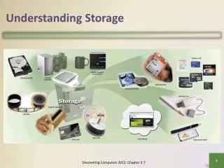
Types of Media • There are many types of media: • Hard Copy • Paper and Microfilm • Hand Held Devices • Mobile Phones, PDA and Tablet • CDROM / DVD and Blue Ray • Computer Hard Drives • ATA / SATA / SCSI • Electromagnetic / Solid State • Tapes • Network Devices • Routers, Switches and Firewalls • Printers and Fax Machines 2
Features of Optical • Electric – optical devices, very different from most other storage media • Immune to magnetic fields • EMP effects • X-ray scanners • PSU / speakers etc... • Read with light, written with heat (CD & DVD R /RW) • Sensitive to temperatures above 49°C • Also sensitive to strong light sources IR & UV • (e.g. UV EPROM Erasers) 3
Physical Construction • Thinner printed side • Reflective layer • Dye • Polycarbonate disc.. 4
Physical Construction • Different discs have different forms of construction 5
Physical Construction • A CD-ROM/DVD etc. can be viewed as an asset. Note: The numbers on the clamping ring refer to batch numbers not ID numbers
Physical Arrangement of Data • DVD and CD media consist of a single strand of data arranged in a spiral pattern starting in the centre of the disc (no cylinders or tracks) • CD 3.7 miles • DVD 7.8 miles • Information on the spiral is spaced linearly so the disc speed has to alter to maintain a uniform flow of data – some drives reach speeds of 5000 rpm. Very similar in overall construction key feature is the way data is packed in a DVD much tighter as the wavelength of the laser is shorter 630-650nm as opposed to 780nm 8
Optical Media File Systems • A number of file systems exist – completely different from magnetic media system • Discs can contain multiple file systems on different areas of the disc • The ‘standard’ ones are: • DVD – UDF • CD – ISO9660 • Have to also consider • Audio discs do not have a file system • Phillips CD Text discs - store text in sub channels • Although there are no partitions, cylinders etc. CD’s and DVD’s have ‘sectors’, 2,352 bytes for CD’s 2048 for DVD’s 9
Disk Drive Technology • Hard disks may originate in the actual device or may be used as external storage. Several types of device and connector SCSI, ATA Etc.. 10
Disks from the Outside • Manufacturers labels: Serial Number, Disk Size, Model / Type, Jumper settings (M.S.CS). • Plus other useful information: • Date of manufacture • Country of manufacture • Firmware edition • Model Information WD1200JB-32AAA0 12000 Is the capacity JB are family and rotation speed (J) and interface (B) (AA) describes the PCB design of the hardware 11
Disks from the Outside • The PCB has a number of key components: • CPU microchip • A motor controller microchip • ROM microchip • Various components for controlling voltages etc. including fuses. • The CPU, ROM and Motor controller chips all have some form of manufacturer marking which can be used to identify possible replacements. 12
Disks from the Inside • A modern HDD is a complex device with a number of internal components, these include: platters, head armature, voice coil, magnet, read / write heads, motor, mountings and air-filters. 13
Inside the Hard Disk • The sector is the smallest addressable unit. • A specific sector can be found addressed by using the cylinder address (C) the Head (H) and the Sector (S). • The CHS method has been replaced by the Logical Block Address (LBA) method which assigns a sequential address to each sector (but which may not relate to it’s physical location) 15
DCO & HPA • HPA and DCO • Host Protected Area (HPA) Can be identified by commands READ_NATIVE_MAX_ADDRESS which provides total sectors on the disk and IDENTIFY_DEVICE which provides total sectors a user can identify • Device Configuration Overlay (DCO) similar to the HPA and can exist at the same time. Can be detected using READ_NATIVE_MAX_ADDRESS and DEVICE_CONFIGURATION_IDENTIFY To capture all of the data on the disk the HPA and DCO may need to be removed. DEVICE_CONFIGURATION_IDENTIFY READ_NATIVE_MAX_ADDRESS IDENTIFY_DEVICE DCO HPA Firmware User Area 17
DCO & HPA • The Host Protected Area (HPA) is defined as: • A reserved area of the Hard Disk Drive. It was designed to store information in such a way that it can not be easily modified, changed, or accessed by the User, BIOS or OS. • The area can contain information ranging from HDD utilities, to diagnostic tools, as well as boot sector code. • The Device Configuration Overlay (DCO) allows system vendors to purchase hard disks (HDD) from different manufactures and potentially different sizes, an then to configure all HDDs to have the same number of sectors. • An example of this is using a DCO to make a 500GB hard disk look like a 320Gb hard disk. • This is used in RAID storage arrays. 18
The Role of Firmware • Firmware performs a number of key functions • Defect control Via P and G lists • LBA to CHS mapping (U list) • SMART logs • + Others; Device Model Number, capacity etc… • Some of these can be manipulated possibly to the advantage of a suspect possibly by an investigator recovering a disk. 19
The Role of Firmware • No disk is manufactured flawless, there will be some sectors on the drive which can not be used. • At the time of production these flaws are recorded in the disk firm as the ‘P’ (permanent / primary / production) list. • This is called the P-List • As the disk ages and through wear & tear other sectors may fail – this is recorded in the ‘G’ (growth) list. This is transparently handled by the disk and occurs ‘beneath’ the operating system. • This is called the G-List • The potential impact in terms of forensic recovery: • The G-list may become full and as a result the disk may stop working* • When wiping the disk the sectors in the lists are not seen by the OS so data may be left on these bad sectors • It may also be possible to manipulate these lists to conceal information in a ‘bad’ sector the potential for steganography 20
The Role of Firmware • Self-Monitoring, Analysis, and Reporting Technology (SMART) is aimed at predicting drive failure. • Par of an earlier ATA standard it has a number of criteria which are monitored and logged as "threshold not exceeded" or “threshold exceeded“ Attributes include read error, seek error temperature… • The Smart attributes monitored depends on the manufacturer, the following all implement some level of SMART: 21
Properties of SSD • Solid state storage has the following characteristics: • Lowest possible access times: SSS offers access times 100 to 1000 times faster than mechanical drives. • High bandwidth: Solid state storage can achieve multiple gigabytes (GB) per second of random data throughput. • High IOPS: SSS offers extraordinarily high random input/output (I/O) performance because of its low access times and high bandwidth. • Low price for performance: SSS provides the best possible price/performance of all storage devices. • High reliability: SSS offers the same levels of data integrity and endurance as other semiconductor devices 23
SSD Elements • So the Basic SSD implement: • Encryption of data blocks being written to Flash memory – AES Encryption • Raid stripping of data across Flash memory cells • Wear levelling at the Flash memory cell level. 24
Wear Levelling • There are three basic types of wear leveling mechanisms used in Flash memory storage devices: • No wear leveling • A Flash memory storage system with no wear leveling will not last very long if it is writing data to the flash. Without wear leveling, the Flash controller must permanently assign the logical addresses from the Operating System (OS) to the physical addresses of the Flash memory. • Dynamic wear leveling • The first type of real leveling is called dynamic wear leveling and it uses a map to link Logical Block Addresses (LBAs) from the OS to the physical Flash memory. Each time the OS writes replacement data, the map is updated so the original physical block is marked as invalid data, and a new block is linked to that map entry. Each time a block of data is re-written to the Flash memory it is written to a new location. However, blocks that never get replacement data sit with no additional wear on the Flash memory. • Static wear leveling • The other type of wear leveling is called static wear leveling which also uses a map to link the LBA to physical memory addresses. Static wear leveling works the same as dynamic wear leveling except the static blocks that do not change are periodically moved so that these low usage cells are able to be used by other data. This rotational effect enables an SSD to operate until most of the blocks are near their end of life. 25
Wear Levelling Free Block Pool . . . 1 Write Request 2 Data Placement 3 Data Block Pool . . . Select Block with Least Number of Valid Pages for Garbage Collection After successful erase, blocks returned to free block pool 27
The RAID File System • A Raided File system is all about reliability and scalability 28
The RAID File System • RAID 3 • In RAID 3 (byte-level striping with dedicated parity), all disk spindle rotation is synchronized, and data are striped so each sequential byte is on a different drive. Parity is calculated across corresponding bytes and stored on a dedicated parity drive. Although implementations exist RAID 3 is not commonly used in practice. • RAID 4 • RAID 4 (block-level striping with dedicated parity) is equivalent to RAID 5 except that all parity data are stored on a single drive. In this arrangement files may be distributed among multiple drives. Each drive operates independently, allowing I/O requests to be performed in parallel.[citation needed] • RAID 4 was previously used primarily by NetApp, but has now been largely replaced by an implementation of RAID 6 (RAID-DP). • RAID 5 • RAID 5 (block-level striping with distributed parity) distributes parity along with the data and requires all drives but one to be present to operate; the array is not destroyed by a single drive failure. Upon drive failure, any subsequent reads can be calculated from the distributed parity such that the drive failure is masked from the end user. RAID 5 requires at least three disks. 29
Questions 30