Download
1 / 22
230 likes | 367 Vues
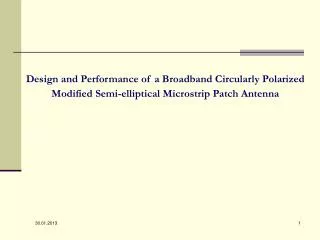
Design and Performance of a Broadband Circularly Polarized Modified Semi-elliptical Microstrip Patch Antenna. Microwave Lab., Department of Physics, University of Rajasthan, Jaipur -302004.

E N D
Design and Performance of a Broadband Circularly Polarized Modified Semi-elliptical Microstrip Patch Antenna
Microwave Lab., Department of Physics, University of Rajasthan, Jaipur -302004 • The presentation is divided in the following sections: • Introduction • (ii) Design and Analysis of Semi Elliptical patch antenna • (iii) Design and Analysis of Modified Semi Elliptical patch antenna • (iv) Conclusions
Microwave Lab., Department of Physics, University of Rajasthan, Jaipur -302004 Introduction • Microstrip antenna is a sandwich of two parallel conducting layers separated by a single thin dielectric substrate, the lower conductor functions as a ground plane and the upper conductor may be simple patch of any desired shape. • Usually made on PCB • Low profile, conformable to various surfaces, inexpensive, durable, but narrow-band • Modify the shape to broaden the bandwidth * Side View Top View Some common shapes of microstrip antenna geometries
Microwave Lab., Department of Physics, University of Rajasthan, Jaipur -302004 Advantages/Disadvantages of Microstrip Antenna: .
Microwave Lab. Department of Physics, University of Rajasthan, Jaipur -302004 Techniques for overcoming Disadvantages: Conventional techniques Non conventional techniques 1- Decreasing dielectric constant of substrate 2- Increasing substrate thickness 3- Application of air gap. 1- Aligned parasitic elements 2- Using stacked parasitic elements.
Microwave Lab., Department of Physics, University of Rajasthan, Jaipur -302004 Recent applications of microstrip antennas in communication electronics • Military Applications • Space Applications • Mobile communication systems • Application in modern wireless systems • Integration with electronic circuitry for different • applications
Microwave Lab., Department of Physics, University of Rajasthan, Jaipur -302004 Design and Analysis of Semi Elliptical patch antenna In this paper, a semi-elliptical patch antenna is modified to achieve circularly polarization with broadband performance. • The semi-elliptical patch in its original shape has radius of semi major axis and semi minor axis equal to 23.1 mm and 13.9 mm respectively. • For designing this antenna, glass epoxy FR-4 substrate (permittivity єr = 4.4, loss tangent tanδ = 0.025 and substrate height h = 1.59 mm) is applied. • The antenna is fed through SMA connector associated with 50 ohm feed line by selecting proper inset feed location on the patch geometry. Structure and side view of Semi Elliptical patch antenna
Microwave Lab., Department of Physics, University of Rajasthan, Jaipur -302004 Variation of Return Loss with Frequency for Semi Elliptical Patch Antenna This antenna resonates at two different frequencies 2.87 GHz and 3.19 GHz with impedance bandwidths close to 80MHz (2.8%) and 110MHz (3.11%) respectively.
Microwave Lab., Department of Physics, University of Rajasthan, Jaipur -302004 Variation of Input Impedance with Frequency for Semi Elliptical patch antenna The variation in input impedances of antenna with frequency is shown in figure, which also provided the excellent matching between antenna and 50 ohm impedance of feed network.
Microwave Lab., Department of Physics, University of Rajasthan, Jaipur -302004 Variation of Axial Ratio with Frequency for Semi Elliptical Patch Antenna The minimum value of axial ratio achieved with this geometry is 8.92dB which is obtained at 3.02 GHz. The variation of axial ratio with frequency indicates that the radiations are linearly polarized as the axial ratio presented by antenna in the selected frequency range is always higher than 3db.
Microwave Lab. Department of Physics University of Rajasthan Jaipur -302004 Figure 5. Variation of Total Gain with Frequency for Semi Elliptical Patch Antenna The gain of antenna is also low (close to 2dBi) at both resonance frequencies. These low impedance bandwidth and gain values suggest that this antenna in its present form is not suitable for modern communication system.
Microwave Lab. Department of Physics University of Rajasthan Jaipur -302004 Design and Analysis of Modified Semi Elliptical Patch Antenna • The semi-elliptical patch geometry is therefore modified by inserting a D-shaped slot. • The straight edge of this slot is orthogonal to the straight edge of semi-elliptical patch. • The thickness of curved portion of slot is 1mm. • The inner and outer radii of the curved portion of inserted slot are 5.1mm and 6.1 mm respectively. • The antenna is fed through SMA connector associated with 50 ohm feed line by selecting proper inset feed location on the patch geometry. Top View of modified semi-elliptical patch antenna
Microwave Lab. Department of Physics University of Rajasthan Jaipur -302004 Variation of Return Loss with Frequency for Modified Semi Elliptical Patch Antenna The achieved resonance frequencies in this case are 2.49GHz and 3.02GHz respectively. In this way, the resonance frequencies of antenna are reduced marginally. With proposed modification, we have therefore achieved a marginally reduced size patch element. At two resonance frequencies, the impedance bandwidths are close to 120MHz and 160MHz which are still very low.
Microwave Lab. Department of Physics University of Rajasthan Jaipur -302004 • We therefore further modified this antenna by replacing single layered substrate material by three layered substrate materials. • Two FR4 substrate materials are separated by a foam substrate of 1mm thickness as shown in figure. • With the present arrangement, the effective permittivity and loss tangent of the substrate reduces considerably and the thickness of entire antenna geometry is less than 5.0mm. Side View of modified semi-elliptical patch antenna with an air pap Top View of modified semi-elliptical patch antenna with an air gap
Microwave Lab. Department of Physics University of Rajasthan Jaipur -302004 Variation of Return Loss with Frequency for Modified Semi Elliptical Patch Antenna with Air Gap Simulated Measured • The Simulated & Measured reflection coefficient results as shown in figure indicate that the resonance frequencies for the two excited modes approached close to each other . • The simulated B. W. of this modified antenna has approached close to 19.54% with respect to central resonance frequency 3.49GHz while the measured impedance B. W. is nearly equal to 18% with respect to central frequency 3.52GHz. • The proposed antenna covers entire median band (3.4 to 3.7GHz) allocated for Wi-Max communication systems.
Microwave Lab. Department of Physics University of Rajasthan Jaipur -302004 Variation of Input Impedance with Frequency for Modified Semi Elliptical Patch Antenna with Air Gap Simulated Measured In order to obtain circularly polarized (CP) radiations, it is necessary to excite two orthogonal modes with equal amplitude and in phase quadrature. This can be accomplished by slightly perturbing a patch at appropriate locations with respect to the feed. With proposed modifications, we realized the presence of a small loop in the input impedance curve of antenna geometry which indicates the possible presence of circular polarization. This result was confirmed by evaluating the axial ratio of antenna as a function of frequency.
Microwave Lab. Department of Physics University of Rajasthan Jaipur -302004 Variation of Axial Ratio with Frequency for Modified Semi Elliptical Patch Antenna with Air Gap The minimum axial ratio is 1.8dB with an axial ratio bandwidth close to 4.63%. This much axial ratio bandwidth is very difficult to achieve with a single layered structure.
Microwave Lab., Department of Physics, University of Rajasthan, Jaipur -302004 E and H-plane Elevation Pattern of Modified Semi Elliptical Patch Antenna with Air Gap These patterns suggest that in each case, shape of radiation patterns and the direction of maximum radiations in the entire band where broadband response is achieved are almost identical.
Microwave Lab., Department of Physics, University of Rajasthan, Jaipur -302004 Variation of Efficiencies with Frequency for Modified Semi Elliptical Microstrip Patch Antenna with Air Gap . The radiation and antenna efficiencies are close to 50%. These low values were expected as for the design of proposed antenna geometry, we have applied glass epoxy FR-4 substrate which has high loss tangent. The efficiency of antenna may be significantly improved by applying better substrate material.
Microwave Lab., Department of Physics, University of Rajasthan, Jaipur -302004 Variation of Total Field Gain With Frequency for Modified Semi Elliptical Microstrip Patch Antenna with Air Gap . The gain of antenna in the frequency range where improved bandwidth is achieved is nearly constant and maximum gain is close to 4.6dBi. 20 30.01.2013
Microwave Lab., Department of Physics, University of Rajasthan, Jaipur -302004 CONCLUSIONS • This paper presents the radiation performance of a modifiedsemi-elliptical patch antenna. • The semi-elliptical patch with D-shaped slot designed on three layered substrate provides broadband behavior. • The simulated and measured impedance bandwidth are 19.5% and 18% respectively which is in close agreement. • The proposed antenna provides circularly polarized radiations with much improved axial ratio bandwidth 4.18%. • The frequency range where improved performance from antenna is achieved lies in the median band of Wi-Max systems. • The results obtained with proposed geometry suggest that this antenna with some more improvements may be proved a useful geometry for modern communication systems. .
Microwave Lab., Department of Physics, University of Rajasthan, Jaipur -302004 THANKS