Reconfigurable Optical Interconnections Using Multi-Permutation Fiber Modules
This paper discusses the development of reconfigurable optical interconnection modules that utilize multi-permutation techniques to alleviate wiring congestion in massively interconnected multi-chip architectures. By exploring a cascaded approach without intermediate optoelectronic arrays, we create a transparent multi-stage architecture suitable for circuit switching in weakly interconnected multiprocessors. The study showcases the efficiency of fiber-based modules and their ability for high-bandwidth performance in routing permutations. Highlights include a detailed analysis of design challenges and potential applications in packet switching networks.

Reconfigurable Optical Interconnections Using Multi-Permutation Fiber Modules
E N D
Presentation Transcript
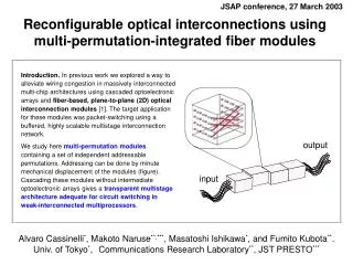
JSAP conference, 27 March 2003 output input Reconfigurable optical interconnections using multi-permutation-integrated fiber modules Introduction. In previous work we explored a way to alleviate wiring congestion in massively interconnected multi-chip architectures using cascaded optoelectronic arrays and fiber-based, plane-to-plane (2D) optical interconnection modules [1]. The target application for these modules was packet-switching using a buffered, highly scalable multistage interconnection network. We study here multi-permutation modulescontaining a set of independent addressable permutations. Addressing can be done by minute mechanical displacement of the modules (figure). Cascading these modules without intermediate optoelectronic arrays gives a transparent multistage architecture adequate for circuit switching in weak-interconnected multiprocessors. Alvaro Cassinelli*, Makoto Naruse**,***, Masatoshi Ishikawa*, and Fumito Kubota**.Univ. of Tokyo*,Communications Research Laboratory**, JST PRESTO***
Introduction Multistage architecture: parallel computers, switching networks + Dense optical interconnect: interconnection folded in 2D… Optical Multistage Architecture Paradigm
Fiber-Modules vs. Free-Space • Fiber have better efficiency (than holograms) for long-range interconnections. • no cross-talk in 3D, just like free-space optics, • No space-invariance possible. • Theoretically more volume efficient than free-space • Precise and robustalignment possible… • multiple interleaved permutations possible. • Maybe “hard” to build? Boring, but not a fundamentally difficult (can be automated, can be done by “layers”). • Alignment ofboth output and input needed… • Power dissipation may be a fundamental limitation, but we are far from these limits… (2) …wave-guide arrays for fixed, point-to-point and space variant interconnections are an interesting alternative to free-space optics 2D folded perfect shuffle permutation module
Fixed inter-stage interconnections… … Interconnection module Interconnection module Interconnection module Optoelectronic processing/switching FIXED interconnections 2D input data flow Photo-detector array VCSEL array Elementary Processor Array …useful for pipeline processing of data (eg. FFT) or packet switching.
… or reconfigurable inter-stage interconnections c3 c4 c2 c1 One or more reconfigurable modules 2D input data flow 2D output data flow … Reconfigurable Interconnection module Reconfigurable Interconnection module High bandwidth transparent circuit-switched networks for permutation routingin multi-processors 16 processors interconnected using the four-dimensional hypercube topology. The network provides four cube permutations c1, c2 , c3, c4
Cascaded Multi-permutation Module Paradigm Cascaded optical permutation modules output input A C : Rem: Dynamic alignment is tightly coupled with dynamic reconfiguration of the interconnect. Cf. Naruse’s presentation. Interleaved fiber-based permutation modules: A small mechanical or optical perturbation can produce a drastic change of the interconnection pattern from input to output! {c2, id} Cascaded multi-permutation modules: This architecture simplifies module design (bi-permutations), while maintaining whole network interconnection capacity. A multistage version of most direct topologies (hypercube, cube-connected-cycles, deBruijn) can be implemented using specially designed interconnection modules.
Module design: layered modules [slide not shown in main presentation] (2) Example: exchange (cube) permutation for N=24 Unfolded [ exchange (k)] (1) (3) (4) {bn, … bk+1, bk, bk-1, … b2, b1} (k) {bn, … bk+1, bk, bk-1, … b2,b1} Folded If k n/2, ((1)and (2))exchange only rows: …If k>n/2, ((3)and (4))exchange only columns. The modules are just the same than previous ones, rotated. Only two modules are needed…
.. But is not always so simple: shuffle permutation [slide not shown in main presentation] (1) = row(1) = id • For N=2=21x20 (n=1) we have : (1) = id (2) = row(1).col(1).L = L • For N=4=21x21 (n=2) we have : (1) = id (2) = row(2)(new) (3) = row(2).col(1).L = row(2). L • For N=8=22x21 (n=3) we have : (1) = id (2) = row(2) (3) = row(2).col(1).L = row(2). L (4) = row(2).col(2).L = row(2). Rrow(2). L • For N=16=22x22 (n=4) we have :
Example: Multistage Spanned Hypercube c4 c3 c3 c4 c1 c2 c2 c1 {c4,id} {c3, id} {c2, id} {c1,id} …topology mapped on a plane (optical interconnects, VLSI integration) four-dimensional hypercube connected multiprocessor… Spanned version of a 4-dimensional weak-interconnected hypercube (16 nodes, 1 bit wide data-bus). It uses four bi-permutation modules, each providing a cube permutation and the identity, which gives a total of 24=16 global permutations for the whole network. Alternatively, using only two of these modules, one can implement an hypercube of dimension 2, with a four bit wide data-bus. “spanned” hypercube using four bi-permutation modules
Time slotted permutation switching Interconnect 1 Interconnect 2 Interconnect 3 Interconnect N Interconnect 1 Interconnect 2 Interconnect 3 Interconnect N Interconnect 1 Interconnect 2 Interconnect 3 Interconnect N Red link Orange link Blue link Green link time Permutation appearance period Time slot
Burst Interconnects Interconnect 1 Interconnect 2 Burst interconnection within “short” time slot (Ex. 10Gbps, 100nsec 1kbit) time Computation one-stage (ex. 1 ms) Interconnection switching interval (Ex. 1ms) = …Slow switching okay
Experiment Setup using two bi-permutation modules. {c2, id} input output {c2, id} {c1, id} Exit first module Input second module Channels are single mode fibers: MFD = 9.5 mGrad diameter 125 m 1 m NA: 0.1 0.01 Module Prototype is not integrated as a single block Displacement stage (piezo) Output (to CCD) Input (from VCSEL array)
Preliminary results Output first two modules (CCD image) …displacement operated manually using a piezo-stage Input (exit VCSEL array) id.id C1. C2 {c2, id} {c1,id} id. C2 Displacement pitch for commutation: 125 m Alignment tolerance: 5 m (half peak power). Inter-module Coupling Efficiency: 1.7dB (no additional optics, matching oil or antireflection coating). Validation ofsimple cascaded architecture. C1. id
Conclusion A C : Multi-function modules: the use of optical fiber modules fits well with the all optical approach; for instance, one can imagine a module with several different interconnection patterns, but also other “optical-functions” like optical delay lines: However, in all-optical networks the “switches” may be very fast (electro optical devices, not MEMS), because the delay time for avoiding the drop of ATM cells is ?? for a typical Gigabit network!!! The switching fabric studied here provides a limited number of long-range, all-optical interconnections useful for high throughput massively interconnected multiprocessors requiring relatively slow switching time (ms range) [ Ongoing research ] • Design and characterization of multi-permutations modules • Architectural considerations: • Modularity / scalability / reusability of modules and systems • Input/output module alignment • Micro-lenses, fibers with round ends. • Modules built from fiber bundles. • Active alignment using electromechanical modules • Applications: • Transparent time division multiplexed permutation network with relatively slow switching time (ms range) • Buffered architecture using bi-permutation modulesfor packet routing. Simulation results are encouraging and besides control simplicity, an additional advantage is that MEMS actuators could be used in AC mode (at their resonant frequencies).
Further research directions • Electro-optical reconfiguration of the interconnection module. • nanosecond range reconfiguration time All optical switching (modules with integrated permutations and directional couplers for instance) must be used if switching speed needs to be orders of magnitude higher. Proposed all-optical bi-permutation switch module • Interconnection + optical function modules • Mixed interconnections, and other optical functions (ex.: delay lines!) References: [1] Cassinelli et al., JSAP 2002. [2] Naruse et al., JSAP spring meeting 2002. [3] Goulet et al., OJ2000, pp.247-248.