Chap 1 – Point-to-Point Protocol (PPP) Learning Objectives
Chap 1 – Point-to-Point Protocol (PPP) Learning Objectives. Describe the fundamental concepts of point-to-point serial communication including TDM, demarcation point, DTE-DCE functions, HDLC encapsulation, and serial interface troubleshooting.

Chap 1 – Point-to-Point Protocol (PPP) Learning Objectives
E N D
Presentation Transcript
Chap 1 – Point-to-Point Protocol (PPP) Learning Objectives • Describe the fundamental concepts of point-to-point serial communication including TDM, demarcation point, DTE-DCE functions, HDLC encapsulation, and serial interface troubleshooting. • Describe PPP concepts including PPP layered architecture, PPP frame structure, PPP session establishment, multiprotocol encapsulation support, link control protocol (LCP), network control protocol (NCP), and Internet Protocol Control Protocol (IPCP). • Configure PPP on a serial interface including enabling PPP encapsulation, verifying the PPP connection and troubleshooting encapsulation problems. • Configure PPP authentication including explaining PAP and CHAP authentication protocols, configuring PPP authentication using PAP and CHAP, and troubleshooting PPP authentication problems.
Transmission Mode Data Transmission Parallel Serial Asynchronous Synchronous
Parallel 8 Bit Input 8 Bit Output Parallel Cables
Each bit is passed over the same conductor, one after the other Serial Output Input Serial Cable
Delay Skew • Each wire has a different propagation delay • Difference between wires is called delay skew • If excessive, data transmitted simultaneously arrives at different times
Cross-talk is interference that is induced into adjacent wires by the • EM field that builds up along cables carrying data • More destructive at higher frequencies • By twisting the pairs together, the EM field reverses every other twist, • cancelling out the induced signal Cross Talk - Cancellation
Serial Interface Standards There are many different serial communication standards, each one using a different signaling method. There are three key serial communication standards affecting LAN-to-WAN connections: • RS-232 - Most serial ports on personal computers conform to the RS-232C or newer RS-422 and RS-423 standards. Both 9-pin and 25-pin connectors are used. A serial port is a general-purpose interface that can be used for almost any type of device, including modems, mice, and printers. • V.35 - Typically used for modem-to-multiplexer communication, this ITU standard for high-speed, synchronous data exchange combines the bandwidth of several telephone circuits. V.35 cables are high-speed serial assemblies designed to support higher data rates and connectivity between DTEs and DCEs over digital lines. • HSSI - A High-Speed Serial Interface (HSSI) supports transmission rates up to 52 Mb/s. Engineers use HSSI to connect routers on LANs with WANs over high-speed lines such as T3 lines. Engineers also use HSSI to provide high-speed connectivity between LANs, using Token Ring or Ethernet. HSSI is a DTE/DCE interface developed by Cisco Systems and T3plus Networking to address the need for high-speed communication over WAN links.
Time Division Multiplexing • Time-Division Multiplexing (TDM) is the transmission of several sources of information using one common channel, or signal, and then the reconstruction of the original streams at the remote end. • One TDM example is Integrated Services Digital Network (ISDN). ISDN basic rate (BRI) has three channels consisting of two 64 kbps B-channels (B1 and B2), and a 16 kbps D-channel.
Statistical time-division multiplexing (STDM) • Developed to overcome the inefficiency of fixed-length time slots in TDM. • STDM uses a variable time slot length allowing channels to compete for any free slot space. • It employs a buffer memory that temporarily stores the data during periods of peak traffic. • STDM does not waste high-speed line time with inactive channels using this scheme.
Demarcation Point – U.S. • The demarcation point, is the point in the network where the responsibility of the service provider or "telco" ends. • In the United States, a telco provides the local loop into the customer premises and the customer provides the active equipment such as the channel service unit/data service unit (CSU/DSU) on which the local loop is terminated.
Demarcation Point – International • In most countries around the world, the network terminating unit(NTU) is provided and managed by the telco. • This allows the telco to actively manage and troubleshoot the local loop with the demarcation point occurring after the NTU. • The customer connects a customer premises equipment (CPE) device, such as a router or frame relay access device, into the NTU using a V.35 or RS-232 serial interface.
DTE-DCE • The CPE, which is generally a router, is the DTE. The DTE could also be a terminal, computer, printer, or fax machine if they connect directly to the service provider network. • The DCE, commonly a modem or CSU/DSU, is the device used to convert the user data from the DTE into a form acceptable to the WAN service provider transmission link.
Cisco Serial DB-60 Cisco Smart Serial Router Serial WAN Connectors To support higher port densities in a smaller form factor, Cisco has introduced a Smart Serial cable. The router interface end of the Smart Serial cable is a 26-pin connector that is significantly more compact than the DB-60 connector.
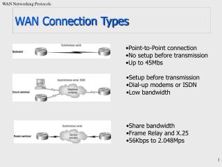
WAN Encapsulation Protocols • On each WAN connection, data is encapsulated into frames before crossing the WAN link. The choice of protocol depends on the WAN technology and the communicating equipment. • HDLC - The default encapsulation type on point-to-point connections, dedicated links, and circuit-switched connections when the link uses two Cisco devices. • PPP - Provides router-to-router and host-to-network connections over synchronous and asynchronous circuits. PPP works with several network layer protocols, such as IP and IPX. PPP also has built-in security mechanisms such as PAP and CHAP. • Serial Line Internet Protocol (SLIP) - A standard protocol for point-to-point serial connections using TCP/IP. SLIP has been largely displaced by PPP.
HDLC Encapsulation 1 byte 1 or 2 bytes 1 or 2 bytes Variable 2 bytes 1 byte • HDLC uses synchronous serial transmission providing error-free communication between two points. • HDLC defines a Layer 2 framing structure that allows for flow control and error control using acknowledgments and a windowing scheme. • Standard HDLC does not inherently support multiple protocols on a single link, as it does not have a way to indicate which protocol is being carried. • PPP actually uses HDLC as a basis for encapsulating data. Flag Address Control Data FCS Flag 01111110 01111110
Cisco HDLC Encapsulation 1 byte 1 bytes 1 or 2 bytes 2 bytes Variable 2 bytes 1 byte Flag Address Control Data FCS Flag Type 01111110 01111110 • HDLC is Cisco's default layer-2 encapsulation for serial lines. This implementation is very streamlined, as there is no windowing or flow control, and only point-to-point connections are allowed. • Cisco HDLC inserts a 2-byte proprietary type code is after the control field. This means that Cisco HDLC framing is not interoperable with other vendors' equipment.
Configuring HDLC • The default encapsulation method used by Cisco devices on synchronous serial lines is Cisco HDLC. • Cisco HDLC is a point-to-point protocol that can be used on leased lines between two Cisco devices. • When communicating with a non-Cisco device, PPP is a more viable option.
Troubleshooting a serial interface Indicates the state of the interface, and the encapsulation used. Indicates the state of the interface channels and whether a cable is attached to the interface
Point-To-Point Protocol (PPP) • PPP's frame format is based on the HDLC frame format put forth by the International Organization for Standardization (ISO). • Unlike the HDLC frame for the ISO, the PPP frame defines a protocol field. • PPP protocols follow open standards and are almost always compatible. • PPP is the protocol of choice when configuring serial links in a multi-vendor environment. • PPP can support multiple Layer 3 protocols, such as IP, IPX, and AppleTalk. • PPP can be configured on Asynchronous serial, Synchronous serial, HSSI & ISDN physical interfaces.
PPP layered architecture NCP PPP contains two sub-protocols: • Link Control Protocol (LCP) – Used for establishing the point-to-point link over the WAN • Network Control Protocol (NCP) – Used for configuring the various network layer protocols. LCP
PPP layered architecturePhysical Layer • PPP operates across any DTE/DCE interface (RS-232-C, RS-422, RS-423, or V.35). • The only absolute requirement imposed by PPP is a duplex circuit, either dedicated or switched, that can operate in either an asynchronous or synchronous mode, that is transparent to the PPP link layer frames.
PPP layered architectureDatalink Layer • The LCP provides automatic configuration of the interfaces at each end, including: • Handling varying limits on packet size • Detecting common mis-configuration errors • Terminating the link • Determining when a link is functioning properly or when it is failing
PPP layered architectureNetwork Layer • PPP permits multiple network layer protocols to operate on the same communications link. For every network layer protocol used, PPP uses a separate NCP. • For example, IP uses the IP Control Protocol (IPCP), and IPX uses the Novell IPX Control Protocol (IPXCP).
PPP Session Establishment PPP session establishment progresses through three phases: • Link establishment • Authentication • Network layer protocol phase
PPP Session Establishment (Detail) 1. Link establishment - (LCPs) 2. Authentication - Optional (LCPs) 3. Link quality determination - Optional (LCPs) 4. Network layer protocol configuration (NCPs) 5. Link termination (LCPs)
Configuring PPP Router#configure terminal Router(config)#interface serial 0/0 Router(config-if)#encapsulation ppp • Enables PPP encapsulation on serial interface 0/0
Configuring Compression Router(config)#interface serial 0/0 Router(config-if)#encapsulation ppp Router(config-if)#compress [predictor|stac] • Point-to-point software compression can be configured on serial interfaces that use PPP encapsulation. • Compression is performed in software and might significantly affect system performance. • Compression is not recommended if most of the traffic consists of compressed files.
Configuring Link Quality Monitoring Router(config)#interface serial 0/0 Router(config-if)#encapsulation ppp Router(config-if)#ppp quality percentage • Link Quality Monitoring (LQM) is available on all serial interfaces running PPP. • LQM will monitor the link quality, and if the quality drops below a configured percentage, the link will be taken down. • The percentages are calculated for both the incoming and outgoing directions.
The show interfaces command reveals the LCP and NCP states under PPP configuration. • The PPP link remains configured for communications until LCP or NCP frames close the link or until an inactivity timer expires or a user intervenes. LCP NCP
Debug PPP command options • Packet – displays PPP packets being sent and received. • Negotiation – Displays PPP packets transmitted during PPP start-up, during the options negotiation phase. • Error – displays protocol error statistics associated with PPP connection and negotiation. • Authentication – Displays authentication protocol messages, including CHAP & PAP exchanges. • Compression – useful for obtaining incorrect packet sequence number information when compresion is enabled.
PPP Authentication • PAP is a very basic two-way process. There is no encryption -the username and password are sent in plain text. If it is accepted, the connection is allowed. CHAP is more secure than PAP. It involves a three-way exchange of a shared secret.
Password Authentication Protocol (PAP) • PAP provides a simple method for a remote node to establish its identity, using a two-way handshake. • After the PPP link establishment phase is complete, a username/password pair is repeatedly sent by the remote node across the link until authentication is acknowledged or the connection is terminated. • The remote node is in control of the frequency and timing of the login attempts.
Configuring PAP R1 R2 172 . 25 . 3 . 0 / 24 DTE DCE . 2 / S 0 Serial . 1 / S 0 hostname R1 username R2 password R2cisco interface Serial0 ip address 172.25.3.2 255.255.255.0 encapsulation ppp ppp authentication pap ppp pap sent-username R1 password R1cisco hostname R2 username R1 password R1cisc0 interface Serial0 ip address 172.25.3.1 255.255.255.0 encapsulation ppp ppp authentication pap ppp pap sent-username R2 password R2cisco • Notes: sent-username and password must match local username and password. • Usernames and Passwords are case-sensitive, hostnames are not involved.
Challenge Handshake Authentication Protocol (CHAP) • The remote node responds with a value calculated using a one-way hash function, which is typically Message Digest 5 (MD5), based on password and challenge message. • The local router checks the response against its own calculation of the expected hash value. • If the values match, the authentication is acknowledged, otherwise the connection is immediately terminated.
Challenge Handshake Authentication Protocol (CHAP) • CHAP is used at the startup of a link and periodically verifies the identity of the remote node using a three-way handshake.
Configuring CHAP R1 R1 172 . 25 . 3 . 0 / 24 DTE DCE . 2 / S 0 Serial . 1 / S 0 hostname R1 username R2 password R2cisco ppp chap hostname R1 (optional) interface Serial0 ip address 172.25.3.2 255.255.255.0 encapsulation ppp ppp authentication chap hostname R2 username R1 password R1cisco ppp chap hostname R1 (optional) interface Serial0 ip address 172.25.3.1 255.255.255.0 encapsulation ppp ppp authentication chap • Notes: Hostnames are involved unless the ppp chap hostname command is used, and must match remote router’s username command (not case-sensitive). • Passwords are case-sensitive and must match
Debug PPP authentication The debug ppp authenticationcommand displays the authentication exchange sequence.
Chap 1 – Point-to-Point Protocol (PPP) Learning Objectives • Describe the fundamental concepts of point-to-point serial communication including TDM, demarcation point, DTE-DCE functions, HDLC encapsulation, and serial interface troubleshooting. • Describe PPP concepts including PPP layered architecture, PPP frame structure, PPP session establishment, multiprotocol encapsulation support, link control protocol (LCP), network control protocol (NCP), and Internet Protocol Control Protocol (IPCP). • Configure PPP on a serial interface including enabling PPP encapsulation, verifying the PPP connection and troubleshooting encapsulation problems. • Configure PPP authentication including explaining PAP and CHAP authentication protocols, configuring PPP authentication using PAP and CHAP, and troubleshooting PPP authentication problems.
Any Questions?
Chapter 2.5.1 – Basic PPP Config R2 R3 R1 Lab Topology Lo0 209.165.200.225/27 S0/0/0 S0/0/1 DCE .2 .1 10.1.1.0/30 10.2.2.0/30 S0/0/0 DCE S0/0/1 PC3 192.168.30.10/24 PC1 192.168.10.10/24 .2 .1 Fa0/1 Fa0/1 192.168.10.1/24 192.168.30.1/24